Theme editor

Scale Model Shop

Build along with Wonwing from start to finish -Hawker Tempest V

Status
Not open for further replies.

wonwinglo

New member
Joined
Apr 18, 2004
Messages
5,410
Reaction score
0
Points
0
1/3
Thread owner
My next subject is this Westwings ( obsolete no longer trading) model of the Hawker Tempest V.
Today will see some parts cut out in preparation for the build,as usual the kit will form the basis for a much improved flying model,my first Tempest model was a kit by Skyleader built at the age of 9,pure nostalgia and I still have the plans for that plus a set of parts that were cut out for it to make a replica model something that I like doing.
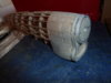
So prior to picking up a sharp knife to cut parts here is a look at the kit as it stands,very basic but all I need to build a dream model.

P1060041.JPG

P1060042.JPG

P1060040.JPG

P1060038.JPG

P1060037.JPG
 
Thread owner
The parts spread for the Hawker Tempest V all cut out from the sheets and ready to make a start today on the fuselage,cut the parts out with great care and you will be rewarded with a smooth build that is the aim,so this is where we are at with parts laid out in shallow card trays all ready to identify and pick.

P1060043.JPG

P1060045.JPG

P1060046.JPG

P1060047.JPG

P1060048.JPG

You can see what is involved with the cutting operation from the scrap wood removed.
 
Thread owner
The keel is laid down and the first formers are carefully added to the master side,tiny gussets have been used to ensure the formers do not lean a common issue with thin balsa formers at this crucial stage of construction,no matter how careful you are this happens and the small gussets is a way of support during the curing process of the adhesive which can pull them out of line.

P1060051.JPG

Down go the keels pinned to the board.

P1060056.JPG

One by one formers are added from nose to tail working slowly and carefully as this is a delicate stage of construction.

P1060060.JPG

P1060061.JPG

And there we have the first stage all ready for stringering once everything is fully dry overnight.
 
Thread owner
Having got soaked yesterday at Weston Park model show it was good to get back in the comfort of my studio to do some work on the Tempest,the port side was stringered from nose to tail as can be seen in the pictures,as usual a few notches for the formers were out of line and the common error was rectified by re notching and a little balsa work to fill the voids,this is no big deal as these kind of things happen and plan design errors creep in,the important thing is to ensure the stringers run smooth and straight with tiny adjustments made along the way,there is always a workable solution in model building so never ever get upset you are the model builder who uses his/her skills to put things to right.
Once the lower nose blocks are in shape and have set the fuselage half can be carefully sanded and the starboard side started by adding more formers.
Once you get to this stage at least you have some strength to work on but it is delicate but rewarding work.

P1060062.JPG

The Tempest fuselage in its early stages of construction today,the rear motor peg support has been added.

P1060063.JPG

P1060065.JPG

Tiny correction pieces added between the formers solves the voids,once sanded you will not notice them,balsa block is for lower nose but I will be sheeting in the nose portion anyway as my usual practise,why add ballast up front when you can add extra shape and strength ?
 
Thread owner
Now we have a secure port side it is time to start building the starboard side up by adding the respective formers from nose to tail,once again keeping everything at exact right angles is important so the use of small gussets is paramount,a tiny gusset locks the former into place and avoids sway when placing the stringers into the slots,besides the gussets a small strip of wood assists in locking the former straight while the adhesive sets.

P1060067.JPG

Starting at the nose working on each half former.

P1060068.JPG

Working cleanly and checking every single joint,these kind of models rely on collective joints,the system is time proven.

P1060076.JPG

Line everything up carefully.

P1060078.JPG

A Tempest takes shape.

P1060073.JPG

The stringers underneath the wings are added after the wing has been assembled to the fuselage.
 
Thread owner
The fuselage is now all stringered up ready for a good sanding,then additional balsa will be added to the nose area fitting between each stringer to add lots of shape and strength rather than additional dead weight for ballast,the only block balsa supplied is for the lower nose area as shown with rough cut blocks awaiting sanding,the lovely shape of the Tempest V nose will benefit from this worthy addition.
The nose block has been laminated together,the existing circular nose plug will be replaced with a more practical and adjustable square nose block,this will be useful for flight trimming adjustments to the thrustline of the propeller,more on that later as lots of changes in that area.
So after a good drying session some sanding will take place to pull the fuselage into fine fettle.

P1060079.JPG

Supplied canopy just sat in place to see what it will look like.

P1060080.JPG

Lower chin blocks yet to be shaped and carved.

P1060082.JPG

The mid formers slide around the wing centre section spars then stringering will be completed in that area.

P1060083.JPG

The adhesive curing area on the radiator turntable,note the gusset infills around the cockpit surround.

P1060084.JPG

Nose block laminations,circular hole will be modified for a square built up nose plug.

P1060085.JPG
 
Nice to see some 'old school' aircraft modelling.
Pete
 
Following this like a leach, Barry.
I have the Guillows F4U-4 Corsair - 30" wingspan. It's all framed up, but I don't want to use tissue to cover it. Would it be possible to skin it with thin balsa sheet or perhaps card? It will be static model.

Thanks.
Ron
 
Thread owner
Following this like a leach, Barry.
I have the Guillows F4U-4 Corsair - 30" wingspan. It's all framed up, but I don't want to use tissue to cover it. Would it be possible to skin it with thin balsa sheet or perhaps card? It will be static model.

Thanks.
Ron
Use ordinary cartridge paper applied with PVA adhesive,once painted it looks like aluminium panels,I once did an A-26 Invader this way.
 
Thread owner
The day has been spent sheeting in between the nose areas with balsa,when doing this cut pieces with a slight wedge to them and press into place firmly as the pieces automatically expand into the voids,once dry sand flush with the stringers,as you can see here it has worked well on the Tempests nose because of the complex pulled in shape at the front,it makes the noses of these type of models look much better and stronger too where needed.

P1060098.JPG

P1060088.JPG


P1060099.JPG

P1060100.JPG

P1060101.JPG


P1060102.JPG


Next the laminated nose is added ready for further sanding and blending in
 

Attachments

  • P1060103.JPG
    P1060103.JPG
    2.2 KB · Views: 0
Thread owner
The laminated nose block has been glued into place and the nose given an initial sanding,now I have devised a important and practical modification and that is to replace the plastic nose button with a squared block that has a vintage brass motor shaft screwed into place,once I sort out some cup washers then the shaft will be assembled to the propeller and worked out,my plan is also to make my own carved three bladed wooden propeller a task that I usually do on most of my models,carving propellers is an art form and requires skill and patience,if you were my apprentice then you would only be considered time served if you had carved a minimum of 100 propellers including three/four and five bladed examples !

P1060104.JPG

P1060106.JPG
 
Thread owner
We can leave the nose assembly for completion later,I have some better ideas than the items supplied with the kit for the spinner assembly.
Meanwhile we can move onto the wings which despite being fairly straightforward the instructions if followed is not the best way to do them,they leave the dihedral joint unglued until the wing has been built however this leads to a flimsy wing during the build and would hamper sanding and clean up,instead I have built the wings as one piece ignoring the dihedral joint for the time being and treating everything as a single wing before the dihedral has been cracked in and re-inforced,that way it will be much easier to handle,a better approach would have been to have made the centre section as one then the two outer wing panels separate which could have been butt jointed on then gusseted,all kits tend to skimp on things to save a few extra parts and this is one example of this.

P1060107.JPG

First job was to laminate the two leading edges from two strips of balsa.

P1060109.JPG

Then lay out the parts required and pre cutting the spars.

P1060112.JPG

Lots of the usual re-inforcement gussets that are sanded in later when everything is set.

P1060113.JPG

All that remains of the parts box,its a basic model but you still have to put the work in,do not be fooled by the relative simplicity,it is the challenges that count.

P1060111.JPG

The area where the wheel well is can be worked on when the wing is cleaned up and turned over,the thick gussets are sanded in with the trailing edge and add a lot of extra gluing area and strength.
 
Thread owner
At last a break in the weather and it has stopped raining long enough to do some messy sanding outside,the wings were lifted from the building board and the leading edges carefully planed and sanded to taper,the tailplane was laid down this morning also and then the wing cranked with its dihedral and the wingtips setting up with suitable blocks while the adhesive dries,then small gussets will be added at the breaks for extra strength.
A suitable former in the shape of a marker pen was used to wind glued paper around to form the basis of the tailwheel doors,then the doors were made by cutting in situ on the former to make two halves.

P1060122.JPG

The wing yet to be dihedraled shown sitting underneath the fuselage for a check fitting.

P1060123.JPG

P1060124.JPG

P1060126.JPG

The wings are cracked at wing rib W4 and suitable blocks placed underneath the wingtips,once set gussets will be added at the breaks,in the foreground the tailplane is setting

P1060120.JPG

P1060119.JPG

Notepaper is rolled and glued around a pen to make the basis of the curved tailwheel doors shown cut out below.

P1060125.JPG
 
Thread owner
With a tiny amount of trimming the wing slid straight onto the fuselage formers and after a light sanding on the aft former slipped cleanly into place,not bad when you consider paper plan shrinkage on any drawing,after a bit of adhesive it was left to set and then the two wing fillet pieces were glued back onto the lower formers,these form the seat for the paper wing fillets.
The tail fin was made up ready for sanding and installation with the tailplane.

P1060131.JPG

The wing went snugly into the fuselage opening,some lower stringering to complete.

P1060129.JPG

You can just see the root end fillets in this view,extra diagonal braces have been added to prevent wing warps in outer panels,light and effective.

P1060128.JPG

P1060130.JPG

Laying down the fin and rudder.
 
Status
Not open for further replies.
Back
Top