Theme editor

Scale Model Shop

Another Parnall Elf

Status
Not open for further replies.

Greyhead

New member
Joined
Oct 13, 2004
Messages
581
Reaction score
0
Points
0
1/3
Thread owner
OK HERE WE GO AGAIN NOW UPLOADING MISSING PHOTOS FOR THIS THREAD.


I’ve uploaded all the photos I can but unfortunately there’s quite a few I can’t find.  The links to tutorials don’t work but I can’t figure out how to do that, I’ll keep trying but as I can’t find the tutorial photos anyway I don’t know how useful they’d be!


I'm new to this forum business so if there's a few mistakes along the way please forgive me!!


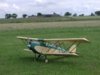
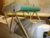
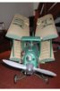
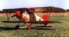
I hope to make this a thread about the construction and flying of a 1/6th scale Parnall Elf. To hopefully whet your appetite, I'll start at the end and post a photo of the finished model. Here goes:


View attachment 263259


The project started about 3 years ago when I was given a pile of free plans from various mags one of which was for the Parnall Elf. I was hooked; a pretty biplane, upright engine, folding wings (No fiddly rigging to contend with) and last but by no means least, not a Tiger Moth!


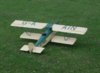
A little bit of research soon revealed that the designer had been stretching the truth a bit when he descibed it as a scale model, so I set about redrawing the plans.


That's enough for now, I'll submit this and if I get any interest shown I'll continue the saga.
 

Attachments

  • EPSN0002 (2014_02_15 10_29_30 UTC).JPG
    EPSN0002 (2014_02_15 10_29_30 UTC).JPG
    2.3 KB · Views: 0
Yes more,we need build and model evolution run downs like this Grahame,I keep thinking this model is so much like my own,more on the construction,wing folding etc please.
 
Keep it coming Greyhead I look forward to hearing the story. From your posted shots it looks to be very well detailed so let us look at a few closeups please.
 
Thread owner
OK, so what was wrong with the plan? Don't get me wrong, I'm not a "rivet counter", but some things have to be right. The plan had top and bottom wings with the same span and the tip shape was wrong, as you can see from this photo it just wouldn't have looked like an Elf in the air!


View attachment 263262


After a trip to the Shuttleworth Collection, armed with the digital camera of course, numerous other less obvious errors were found. I'll not list them here but point them out as the thread progresses.


I intend to develop this thread in the cronological order that I built the Elf but if anyone is building a similar project and thinks I might have an answer to a particular problem let me know and I'll try to help.


I always start construction with the fuselage. Wings are usually fairly straight forward, but that didn't prove to be the case this time!


The first thing is the "heart" of the model, the engine bearers, cabane strut, bottom wing and wheel hard points.


View attachment 263260


Then the sides made from 1/16th ply and the rest of the formers.


View attachment 263261


The cabane brackets are made from 0.5mm galvanised steel, from B&Q, much stronger then brass for these high stress points, the extra weight is minimal. They are fixed to the fuselage using model railway track fixing pins.
 

Attachments

  • EPSN0006 (2014_02_15 10_29_30 UTC).JPG
    EPSN0006 (2014_02_15 10_29_30 UTC).JPG
    2.1 KB · Views: 0
  • ELF_FUS1 (2014_02_15 10_29_30 UTC).JPG
    ELF_FUS1 (2014_02_15 10_29_30 UTC).JPG
    2.5 KB · Views: 0
  • ELF_FRONT (2014_02_15 10_29_30 UTC).JPG
    ELF_FRONT (2014_02_15 10_29_30 UTC).JPG
    2.4 KB · Views: 0
Thread owner
The top of the fuselage was covered with 1/16th balsa leaving the luggage compartment open; I use this hatch as a convenient access point for the rudder and elevator servos, the bottom sheeting was left until after the cockpit detailing was finished. The flat just before the cowl was added later.


Next the tail plane, fin and rudder. Not a lot to say really, I used the popular “core and half-ribs method”, the rudder profile needed changing from a typical “Tiger Moth shape” on the plan to incorporate the distinctive straight TE. On a previous model I designed I got the tail incidence wrong so I decided to make this one variable as per full size, of course sod’s law prevailed and having gone to all that trouble it doesn’t need any adjustment.


Anyone who’s made a biplane knows what a pain cabane struts are. I usually end up with 3 or 4 sets in the bin before I get one that’s near enough to be able to fiddle the fixings to get the correct incidence and level wings. I decided there must be a better way, there is, the way the full size do it! But how to model them?


That’s enough writing; let’s have a photo:


View attachment 263264


The answer proved to be quite simple. They are made from streamlined brass tube with a snake inner going right through the centre, in this case the ends are crimped and then a closed loop adaptor screwed in both ends. The result is a fully adjustable cabane strut ready to be bolted to the brackets using 14BA bolts. Any variation can now be adjusted out and they look a lot more scale.
 

Attachments

  • CENTRE_MOUNT_1 (2014_02_15 10_29_30 UTC).JPG
    CENTRE_MOUNT_1 (2014_02_15 10_29_30 UTC).JPG
    2.7 KB · Views: 0
Thread owner
Before I got to the stage shown in the photo above I needed to know how I was going to hinge the wings to the centre section. This is where the plan was seriously wrong; it had flat plate hinges. Whilst it was obvious using simple geometry that the hinges shown wouldn’t work, it wasn’t quite as obvious what would! Luckily the top hinges are visible and I was able to take a photo at Shuttleworth that gave me a good starting point but it wasn’t completely clear how they worked because of course I couldn’t fold the wings.


I made a jig to see what happens as the wings fold.


View attachment 263271


This confirmed the design; the hinge has to turn in the fuselage fixing. I achieved this by using 4mm bolts with captive nuts in the fuselage and centre section.


View attachment 263272


The end result. No problem getting this in the car!


View attachment 263270


The people at Shuttleworth were very helpful and allowed me to “cross the white line” in order to take the necessary photos. However, if you do visit the collection at Old Warden please don’t abuse their generosity, if every other person says, “I’m building a scale model, any chance of getting closer?” they might change their policy.
 

Attachments

  • HINGE_JIG_2 (2014_01_28 14_36_24 UTC).JPG
    HINGE_JIG_2 (2014_01_28 14_36_24 UTC).JPG
    2.1 KB · Views: 0
  • HINGE_JIG_1 (2014_02_15 10_29_30 UTC).JPG
    HINGE_JIG_1 (2014_02_15 10_29_30 UTC).JPG
    2.1 KB · Views: 0
  • FOLDED (2014_02_15 10_29_30 UTC).JPG
    FOLDED (2014_02_15 10_29_30 UTC).JPG
    2.7 KB · Views: 0
greyhead i have read your thread , i am not an aero modellor but i have found the thread superb !!

very informative m8

more of the same would be great

keep it up !! ;)
 
greyhead i have read your thread , i am not an aero modellor but i have found the thread superb !! very informative m8
Me too, I just wish I had the skill to make something from scratch, but unfortunately kits are the best I can do.

As for the attachments, that's up to you, you can attach them or embed them in your posts, all I ask is that they are no bigger than 640px wide, it just makes the forum look odd and takes a lot longer for the page to load, especially for those on 56k.
 
Grahame

Personally I prefer to have the full res picture with the text without having to click the thumbnail. At the end of the day, assuming you want to see all the pictures, it will take about the same time overall.

It's nice to see with all the ARTF stuff on the market that the skills are still around to scratch build such a model from an inaccurate plan, a trip to the Shuttleworth collection and the few photos of the Elf that are still available.

Keep it up.

David
 
Grahame that sure is a neat idea to do the cabane struts,I will almost certainly use this idea myself in the future,the adjustment is just what is needed.

It is nearly impossible to bend piano wire as accurate as to be spot on for the required decalage on a biplane.

I cannot believe that the plan showed a Tiger Moth tail,just shows the lack of research by that person.

What a pleasure it is to see these constructional pictures of your model,you are a very skillful modeller and we all value your contributions to the forum.

If only more would pick up the digital camera when building their models,it is also good to look back on the construction.
 
Thread owner
Thanks for the replies, I'll certainly now carry on with the thread. I prefer the full size photos to thumbnails but I also wondered about the download time, it's amazing how soon we forget what it was like before broadband. I'll use thumbnails, at least for the next few posts, and see if there's any negative reaction, it also makes it easier for me to upload.
 
Personally I like the full pic first time rather than the thumbs BUT just keep them coming. A great article, as I said in a previous post ..more please. Great solution to wing fold.:terrific:
 
Your wing folding is just spot on,and above all it is functional and practical,you just cannot beat hands on looking at the real thing to see how the designer did it,for anyone who has not attempted a biplane you just dont know what you are missing out on,once built they are very strong and great fun to fly.

Grahame dont let the lack of feedback put you off sending in this info,rest assured there are lots of people interested,it is not that they are ungrateful,think of these excellent practical contributions as assisting people who are perhaps thinking of building their first scale subject,it is all being archived for future posterity,everything that you write will appear on the search engines,so if someone is building a Parnell Elf it will lead them here ! after you have dealt with this one then you can tell us about your Albatross,now there is a tricky building subject.
 
cool dude i prefer the pics in with the text stops you getting lost

this is a really cool porject dude keep up the good work
 
Thread owner
Back to plan A, from the replies it seems that embedded photos are preferred, 3 for, 1 neutral and 0 against. As for the Albatros, that was built in 1998 before I went digital so no construction photos and as I’ve just sold it, no chance of any more. There is however quite a story to the development of the model but it will have to be 99% text. But first I'll finish this thread!!
 
Thread owner
At this stage I’d made the hinges and satisfied myself that they would work but hadn’t started the wings so the photo above is really out of sequence but it’s the only one I’ve got of a finished hinge showing the bolt.


The next job was to furnish the cockpit; one advantage of these early planes is that they were very basic in the instrumentation department. The throttle and fuel switch etc. were made from scrap aluminium or plastic tube and balsa.


View attachment 263273


As mentioned above the floor is yet to be added.


View attachment 263274


I hoped that it would be a simple job to use the photo of the full size panel but unfortunately because of parallax (hope that’s spelt correctly!) some of the dial faces are partly hidden by the bezels and whilst not obvious at first sight, perspective has made the outer dials oval.


View attachment 263275


After spending many a happy hour on Photoshop I produced acceptable dials etc. These were correctly spaced using Publisher and printed out on “Glossy Photo Paper”. The control panel itself is made from card covered with litho plate, the dial printout, a sheet of clear acetate and finally another layer of card. The bezels are cut from card and the “level flight” indicator is a length of Bowden cable outer.


View attachment 263276


The clarity possible using “cheap” technology is amazing, this photo doesn’t do the dial faces justice. I used a high-resolution setting when printing out and, although way “over the top”, it is possible to read the serial number on the rpm indicator using a magnifying glass!
 

Attachments

  • CONTROL_PANEL_2 (2014_02_15 10_29_30 UTC).JPG
    CONTROL_PANEL_2 (2014_02_15 10_29_30 UTC).JPG
    2.5 KB · Views: 0
  • CONTROL_PANEL (2014_02_15 10_29_30 UTC).JPG
    CONTROL_PANEL (2014_02_15 10_29_30 UTC).JPG
    2.6 KB · Views: 0
  • COCKPIT_1 (2014_02_15 10_29_30 UTC).JPG
    COCKPIT_1 (2014_02_15 10_29_30 UTC).JPG
    2.7 KB · Views: 0
  • COCKPIT_2 (2014_02_15 10_29_30 UTC).JPG
    COCKPIT_2 (2014_02_15 10_29_30 UTC).JPG
    2.4 KB · Views: 0
Thread owner
Onto the cowl, my favourite part of any aircraft, they are so individual and have lots of lovely fixings, bumps, air scoops and other odd appendages to stretch our modelling imaginations.


First a photo of the finished article, it can appear a daunting task but taken step at a time it’s OK.


View attachment 263284


A decision has to be made as to whether to cut non-scale holes or use scale inspection hatches to gain access to the engine for choking and adjusting the needle valve etc. In this case the sides are hinged so the choice is fairly obvious although it does complicate the build somewhat. The first step is to make ply formers for the front and rear, with this cowl it was slightly more complex, because of the hinges there are actually 3 formers, top and left and right sides, for both front and rear. The formers are then joined with balsa “longerons” and covered with 1/16th balsa. Wetting the outer surfaces where there are tight bends helps considerably.


The next problem is the long hinge. Commercial “piano” hinges are just too big and won’t bend. You can make your own quite simply by soldering brass tube to brass strip and cutting into suitable lengths.


View attachment 263278


The hinges are glued using epoxy.


View attachment 263279


The result is a very neat joint.


View attachment 263280


That’s enough for today, next time it’s fixings, louvers and exhaust pipe.
 

Attachments

  • COWL_HINGE_1 (2014_02_15 10_29_30 UTC).JPG
    COWL_HINGE_1 (2014_02_15 10_29_30 UTC).JPG
    1.8 KB · Views: 0
  • PIANO_HINGE_FIXED_2 (2014_02_15 10_29_30 UTC).JPG
    PIANO_HINGE_FIXED_2 (2014_02_15 10_29_30 UTC).JPG
    1.8 KB · Views: 0
  • PIANO_HINGE_CONSTRUCTION (2014_02_15 10_29_30 UTC).JPG
    PIANO_HINGE_CONSTRUCTION (2014_02_15 10_29_30 UTC).JPG
    1.4 KB · Views: 0
  • COWL_LEFT (2014_02_15 10_29_30 UTC).JPG
    COWL_LEFT (2014_02_15 10_29_30 UTC).JPG
    2.1 KB · Views: 0
Status
Not open for further replies.
Back
Top