If this is your first visit, be sure to
check out the FAQ by clicking the
link above. You may have to register
before you can post: click the register link above to proceed. To start viewing messages,
select the forum that you want to visit from the selection below.
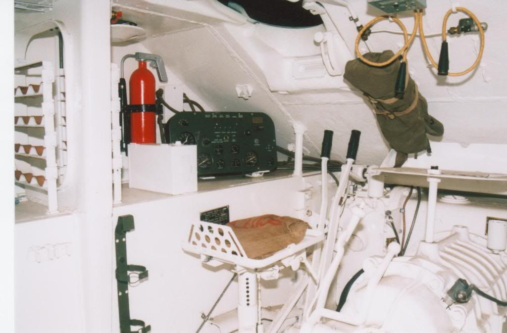
I notice I’ve forgotten to explain what I’ve done to get to what’s in the photo, having gotten too absorbed in imparting wisdom about interior design
Like I said, the transmission is from AFV Club, as are the seats, though their supports aren’t, because in the M10 they were attached to parallelogram brackets bolted to the lower hull sides, while in the M4A4 they sat on top of pillars on the floor. Pretty much everything else than these parts is eyeballed rather than built to exact plans, because all I have to work from are photos from the M4A4’s tech manual (see above for a link), pictures of the Resicast interior set (to be found easily by googling for “M4A4 interior”) and photos of a real Sherman V under restoration on this site (this is part of a series on that site, which seems to start with part 2 of 13; I haven’t been able to find part 1). That last site, by the way, also solved some of the mysteries about the Resicast Multibank engine set: photos from it appear in Resicast’s instructions, and Resicast seems to have modelled much of the pipework after them — when in fact it’s clearly a partially disassembled engine bay. This accounts for the pipe just sort of hanging down on the left side wall, for example, as well as the missing lines between the fire extinguisher nozzles on the sides and those at the rear, and the missing pipe that comes off the fuel filter on the rear plate (compare the TM photo and my modified Asuka kit part with the Resicast one to see what I mean).
Anyway …
The transmission has had some thick plastic strip added to represent the flanges that are there on the three-part transmission but not on the one-piece ones; there should be bolt heads on either side but I don’t think I’ll add them because the flanges are far more obvious through the hatches than any bolts on them. But I might after all …
The floor on the driver’s side is a piece of plastic card embossed with a tread plate pattern that I bought at some point (no idea who made it), with pedals made from some bits of plastic card and strip, and control handles from steel florist wire glued into holes drilled into a short length of sprue. On the real tank these handles were flat strips with round grips, but because you’ll see the narrow side from the hatch, I felt I could get away with using wire, as that’ll hold its shape far better than plastic strip will when bent like this. The rear handle on the transmission (the parking brake lever) is 0.8 mm plastic rod with a knob made at the end by holding it near a flame, and glued to another short bit of sprue. The other handle, the gear shift, is a length of plastic strip with the top shaved down to a round cross-section and a thick disc with button added from plastic card punched out with a punch and die set. The seat pillars are again just lengths of sprue.
The escape hatch mechanism is also pretty simple: another couple pf punched discs in the middle, with some rod to represent the locking bars and a piece of strip for the handle. This hatch turns out to be remarkably visible through the driver’s hatch.
I had to build the drive shaft tunnel myself. I wanted to use the AFV Club part, but that’s horizontal when on the M4A4, the tunnel notably slopes upward. I measured it up in the section drawing in the Tech Manual (page 13, AKA page 21 in the PDF), and though that seems to have been based on a “short-hull” Sherman, it looks like they only shortened the engine, not the rest of the tank, so the drive shaft should be fairly accurate on it. This let me estimate the angle and cut plastic card to suit; the top is a piece of 6 mm tube. It ends halfway through the hull because the lower part of the turret basket will go over it, so the rest won’t be visible anyway. That’s what the transverse piece of card is for: to attach the basket floor to.
The instrument panel is just a piece of plastic card with more punched-out discs for the dials. I’ll probably add a few more smaller bits for the stuff like knobs and dials that were also on it. The little box next to it is an Italeri ammo box from the spares box, used because it’s more or less the right size. The stuff behind the driver’s seat is built from plastic card and doesn’t need to be highly detailed because it won’t be very visible. Something similar, but bigger, will end up behind the escape hatch to represent the ammo bin, but that can only go in after basic painting of the interior for reasons that will become apparent in a later post (I hope).
Finally, the braces in the sponsons consist of a piece of square rod running from floor to roof and some 1.5 mm plastic card with a hole cut in. After drawing the holes onto the plastic with a pencil, I punched out their corners and connected them with a knife before filing everything to clean up the hole. I then rounded the front edge, because on the real tank these were made of stamped steel, not solid pieces.
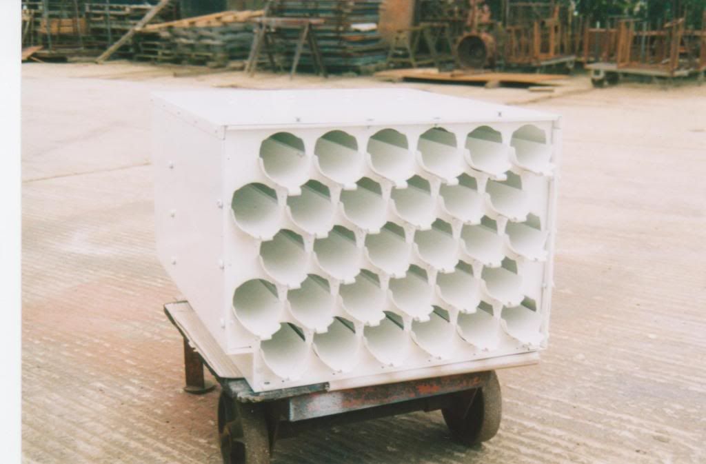
One of my biggest puzzles with this model was how to make the ammunition rack to the left of the driver. On the real tank this is a fairly simple affair made of steel strips to create a kind of very narrow set of shelves, with “wavy” strips of steel as support for the rounds in the rack. This photo from the restored Sherman I linked to above shows what I mean:
The rack itself is easy enough to build from some plastic strip, but those supports gave me quite a bit of trouble before I found a good way to make them. Which I shall now share with you all:—
[ATTACH]298878[/ATTACH]
Yes, I drilled them!
No, of course not. After looking at all kinds of materials I have around my hobby room, and finding nothing suitable, I eventually noticed that the slots in which the drills sit in this box, had the correct spacing for the rack I’d already built from plastic strip. The clear plastic cover from the box was easily removed, so that just left working out how to use the slots to bend material neatly. After a few attempts with various tools, I found that this worked well:
[ATTACH]298879[/ATTACH]
A couple of cocktail sticks that I normally use to apply superglue with. These are big enough that they don’t drop all the way to the bottom of the slots, so I could use them to press each indentation to the same depth. I initially used two, as in the photo, but it soon turned out that three worked better: two could keep the strip in place while I pressed down on the third to make the next “wave” — using only two sticks, the strip tended to turn under the one left in place. Altogether it gives this result:
[ATTACH]298880[/ATTACH]
The material is a 1 mm wide strip that I cut off some 0.2 mm aluminium sheet I obtained many years ago, that had been used for offset printing. (Printers discard the sheets when they’re done with them, but they make excellent material for scratchbuilding.)
Then all I needed to do was make four lengths and glue them into the rest of the ammo rack, to get this:
[ATTACH]298881[/ATTACH]
By now the interior is complete as far as I’m concerned:
[ATTACH]298885[/ATTACH]
[ATTACH]298886[/ATTACH]
The ammo rack can be seen just in front of the brace on the left side of the tank. There should be a second one behind the brace, but it’s barely visible on the model so I left it out. There’s also a bit of diagonal strip fixing the rack to the bulkhead that isn’t there on the real tank, but because the rack otherwise only attached at two very small points at the bottom, I don’t want to run the risk of it coming loose or bending, so I added the strip where it’ll be invisible on the finished model.
The turret basket (a Games Workshop 40 mm wargames base, cut in half) is still loose, as is the ammo bin underneath it on the right-hand side of the drive shaft tunnel, both to ease painting. The bins on the right front are cut from resin waste, which is a very good material if you need blocky shapes. There should be an enclosed ammunition bin behind them, filling the space between the bins and the brace, but this particular tank was a command vehicle and had a radio in the hull instead. Unfortunately I’ve been unable to determine what type of radio that was, but it would most likely have been removed during or after the war, so I feel leaving the sponson there empty won’t be a major inaccuracy.
This is just about impossible to make in 1/35th scale in plastic. The front could probably be done well in photoetch, but from plastic … not with my modelling skills. Unfortunately, though, the holes in it turn out to be pretty visible through the driver’s hatch. So what do you do?
Cheat, is what:
[ATTACH]299311[/ATTACH]
I made the above in Adobe Illustrator (other vector drawing programs are available) to a size that would fit on the front of the plastic box I’d built to represent the ammo rack — that is, 17 mm wide and 10 mm high, though as already mentioned, I had to guess at dimensions.
The graphic itself is just a rectangle with a black stroke (outline) that’s outside the rectangle, with thirty circles on it that are filled with a black-to-white radial gradient whose centre is just below the centre of the circle. (Tip: draw only one circle, then copy it as many times as necessary to make a row, align the left- and right-most ones, and let the program space the rest between them; then group them into a row, copy the group downward as needed, and again auto-space them vertically.)
[ATTACH]299307[/ATTACH]
That's the ammo bin with the printed-out image stuck onto the front, and here’s what it looks like through the model’s driver’s hatch:
[ATTACH]299308[/ATTACH]
Now it’s mostly painted and only needs the seats installed (and the ammo rack and turret floor glued in place), the interior looks like this:
[ATTACH]299309[/ATTACH]
[ATTACH]299310[/ATTACH]
I intentionally tried to make it look pretty dirty and rusty, given that this model represents a tank that’s been sitting out in all weather with its hatches open for several years, and with some worn paint on edges where people would climb in and out of it or grab onto — children would have played in and on the tank, for one.
I’ve finally finished building the engine … I knew going in that it would probably be a bit of a struggle, given that it’s a fairly complex resin kit, and though I’ve built worse resin engines (*cough* AEF Designs M60 MBT engine *cough*), I’m fairly certain that nobody at Resicast has tried putting this engine into a Sherman. Once put together so that it fits, the impression I get is that it’s intended to be displayed outside a tank with an empty engine bay.
I had the engine and radiator painted in their basic colours with some weathering, shading, etc. That had the advantage that it shows very nicely the amount of material I had to remove to allow the engine to fit into the tank:
[ATTACH]300508[/ATTACH]
From the top of the radiator, I had to remove the filler cap and part of the front to get it to fit under the bulge in the forward engine deck, and a bit at the right bottom so it would clear the extra pipes I put in on the sides of the engine bay — even though the radiator fit between those when it wasn’t attached to the engine yet.
At this point I thought I was there. Unfortunately, when I dry-fitted the air intake pipes with the carburettors, they lifted up the rear end of that same forward engine deck by about 2 mm. It turned out that they protruded above the level of the engine deck by a fair amount, and so did the rear end of the work platform on top of the engine, though not by as much. The only solution I found was this:
[ATTACH]300509[/ATTACH]
I sawed off as much of the bottom of the engine and radiator as I could. The engine had a narrower, stepped area on the bottom, which I removed entirely, and the radiator is also missing everything that was below the lower coolant pipes. The only reason I didn’t take off more, is those same cooling pipes. All this is really fun to do with an engine that’s half built and has some fairly fragile parts glued in place … My advice to anyone else attempting to fit the engine inside a Sherman is to just build the basic engine and then see if it fits, before adding any of the detail parts.
Anyway, that solved the issue partially: the engine was now below the engine deck level, but the air intake pipes still protruded above it. This required a couple of different fixes. One was to reduce the height of the undersides of the two carburettors that sit directly onto the upper engines, which allowed all of the carburettors to drop. Another involved cutting away part of the undersides and insides of the thick pipes running over the radiator, as well as the bolts on the upper corners of the radiator. This still didn’t solve it completely, though, because the transverse pipe just fouled the work platform on top of the engine. Filling that down from the front allowed the pipe to sit a little lower, and the engine deck would now sit flush on the hull:
[ATTACH]300510[/ATTACH]
And two views of the nearly complete engine, that’s just missing a few pieces that will be too tricky to paint if they’re attached to the engine:
[ATTACH]300511[/ATTACH]
[ATTACH]300512[/ATTACH]
[ATTACH]300513[/ATTACH]
You can tell in the last picture that I had to do some surgery on the thick pipes at the front, as their ends used to be circular in cross-section
That’s obviously the engine. I used some photos of restored engines I found online as a painting guide, as I couldn’t find any good information on what it would have been painted like when new. Basically, the engine blocks are green, the radiator and piping for coolant and intake air are black, and all the exhaust pipes I painted as if they’re rusted. Additional weathering and wear was then added to the engine as a whole.
Here’s the engine bay it will go into:
[ATTACH]301086[/ATTACH]
I removed the engine support at the rear because it interfered with the engine’s fit and turned out to not be visible anyway with the engine in place. Inside the middle of the three depressions in the floor, I put a piece of 1.5 mm plastic card so I had a surface to glue the engine to.
[ATTACH]301087[/ATTACH]
Now with the engine and firewall glued in place. As I couldn’t reach underneath it, I put a fair amount of superglue onto the plastic card from the previous photo, wiggled the engine into place (which is harder than you think it might be), and trial-fitted the upper hull to make sure it was in the right place. Once I was happy with its fit, I added more superglue underneath the radiator, as that touches the floor but its front side will be invisible anyway. Then the firewall, and finally I decided to put a brace in so the engine can’t come forward even if the glue doesn’t hold it for some reason. This is just a piece of resin sprue of the right width that I glued diagonally to the firewall.
Then came Asuka’s exhaust pipes and ducting. This fits well enough, except that the plastic exhaust pipes neither fit nor line up with the Resicast ones on the engine. I had to cut them down to get to this:
[ATTACH]301088[/ATTACH]
To ensure it would all fit and line up, I drilled a hole into the plastic exhaust pipes and added a short bit of 1 mm brass rod, which fits inside the holes in the resin exhaust pipes. That just left the gap between the resin and plastic pipes, which I solved by adding a tube around the resin pipes from a strip of 0.15 mm plastic card:
[ATTACH]301090[/ATTACH]
[ATTACH]301089[/ATTACH]
Once the plastic parts were also fully painted and installed on the model, it looks good enough for my standards:
[ATTACH]301091[/ATTACH]
Now I can at last get on with the rest of the model …
Jakko
Outstanding work on the engine and compartment. It took a lot of work but was worth it in the end. Where did you put the oily rag?:smiling2:
Steve
Thanks all, but I’m really just a mediocre modeller of no more than average skill :smiling3:
Now, though, I’ve added the deep-wading trunk to the back of the model:
[ATTACH]301555[/ATTACH]
[ATTACH]301556[/ATTACH]
This is by Resicast, and goes together easily enough except for the fact that they had forgotten to pack the two exhaust cover plates, so I had to make them from plastic card (as you can tell by the R written on the visible one) with some punched-out bolt heads. I have another set of this (for a Sherman Crab I intend to build later, also as a post-war derelict vehicle), so that allowed me to get the measurements for them, but even without it would have been easy enough as they’re just plates that close the holes to either side of the wading trunk, with three bolts on each.
Not that much fun were the handles on the removable lower plate. Resicast gives you two sprues of five handles each, for the six that need to go onto the model. Three were already broken, but that ought to have given me enough … but no, of course more broke so that I had to glue the handle back onto one to get the six I needed :unamused:
The set also includes a forward engine deck plate (two, actually, one for a Tasca/Asuka kit and one for Dragon), with waterproofing canvas over the grille and an etched mesh to go on top of that. However, as is visible in the upper picture, I used the plastic engine deck from my Asuka Sherman because on photos of the real tanks, all the canvas has disappeared from the gun mantlet and bow machine gun, so I don’t think any would have been left on the engine deck either. For the same reason, I now have two spare canvas-covered gun mantlets (M34 and M34A1), a ditto a bow machine gun, plus a 75 mm barrel — times three! (Two each from the wading trunk sets, plus one more of each from the Resicast Crab conversion, from which I also won’t use them.)
I’m getting there: by now I’ve added the tool stowage and other details to the rear hull. For completeness, I should probably mention I’ve decided to build the other Sherman V than the one I originally intended to, because more views of different sides of it exist. That’s to say, this one:
[ATTACH]302433[/ATTACH]
As was to be expected, this tank was missing all its tools:
[ATTACH]302432[/ATTACH]
So I had to scratchbuild the tool stowage brackets:
[ATTACH]302430[/ATTACH]
This turned out to be fairly easy with some more leftover photoetched frets and a few photos of real Sherman tool stowage. I first had to fill the holes for the kit’s tools, because many would remain visible underneath the brackets. Then it was mostly a matter of cutting a bit of brass from the fret and bending it into shape. The white bits of plastic strip represent the fire extinguisher brackets.
Other details you may notice are the missing tail light lenses. As this photo shows:
[ATTACH]302431[/ATTACH]
those were stolen or vandalised (I suspect they were removed to take the bulbs out for use elsewhere), so I drilled a hole in the middle of both lamps and them reamed them out with a knife, followed by a drop of liquid cement to smooth the plastic. This photo also seems to show the left rear light guard was missing for some unknown reason, so I left it off.
Other details: the right fuel cap cover is open, since the side and rear views above show it that way, and the keen-eyed may notice I left off the little sloping armour plate on the turret splash ring, just in front of the fuel filler cap. This because the side view of the real tank doesn’t show it either. Instead, I drilled a small drain hole through the splash guard.
Now I need to find good way of making the stowage rack on the hull front. I’m thinking of soldering together brass L-profile — if I can find or make some fine enough and I don’t screw up the soldering


Comment