Morning all,
So I've had my mill for a few months now, the lathe I've had around 4 years. Since I've had the mill I've been busy learning how to use it and decided it was time to actually build something useful. Hemingway supply kits to model engineers, including engines and locomotives, but also sell a number of tooling projects. I already have a purchased knurling tool, but it's not very good, and this clamping style that I'm building should work a lot better.
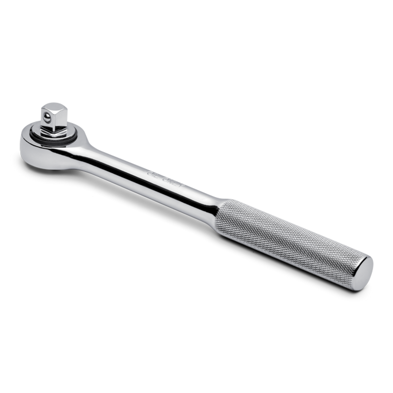
For anyone who doesn't know knurling is the imprinted pattern often found on tool handles, like this:

On to the kit, the box art:

The instructions:

The sprues: 😂

I spent some time on the instructions, this is the first time I've used proper engineering drawings and it took some time to decipher them, particularly as they are in Imperial and I work in Metric.
The first step is the main body, which are the side plates and a spacer block. All parts were machined to dimension, and a number of holes drilled, and in some cases tapped. Two further holes were drilled and reamed to precise dimension which will later take the arm pivots. The rear corners were also knocked off, this will be the operator side so lessens the chance of injury.


The final step to this part is the tool block, this is simply an extension to allow the tool to be mounted to the tool post.


And that little lot took around 6 hours! What I have learned from machining is that most of the time is spent fixturing and measuring, and a small amount actually drilling or cutting.
I am very pleased with the progress however, everything fit perfectly, and is square and true and all the holes lined up perfectly, so I'm doing something right.
Next up are the arms which are far more complex pieces with a number of features to be machined.
So I've had my mill for a few months now, the lathe I've had around 4 years. Since I've had the mill I've been busy learning how to use it and decided it was time to actually build something useful. Hemingway supply kits to model engineers, including engines and locomotives, but also sell a number of tooling projects. I already have a purchased knurling tool, but it's not very good, and this clamping style that I'm building should work a lot better.
For anyone who doesn't know knurling is the imprinted pattern often found on tool handles, like this:

On to the kit, the box art:

The instructions:

The sprues: 😂

I spent some time on the instructions, this is the first time I've used proper engineering drawings and it took some time to decipher them, particularly as they are in Imperial and I work in Metric.
The first step is the main body, which are the side plates and a spacer block. All parts were machined to dimension, and a number of holes drilled, and in some cases tapped. Two further holes were drilled and reamed to precise dimension which will later take the arm pivots. The rear corners were also knocked off, this will be the operator side so lessens the chance of injury.


The final step to this part is the tool block, this is simply an extension to allow the tool to be mounted to the tool post.


And that little lot took around 6 hours! What I have learned from machining is that most of the time is spent fixturing and measuring, and a small amount actually drilling or cutting.
I am very pleased with the progress however, everything fit perfectly, and is square and true and all the holes lined up perfectly, so I'm doing something right.
Next up are the arms which are far more complex pieces with a number of features to be machined.


Comment