Theme editor

Scale Model Shop

HAWKER FURY BIPLANE-complete build sequence 'build A Long with Wonwing'

Status
Not open for further replies.

wonwinglo

New member
Joined
Apr 18, 2004
Messages
5,410
Reaction score
0
Points
0
1/3
Thread owner
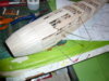
This obsolete kit of the Flair Hawker Fury biplane will form the basis of my next model,the Fury will be built into a lightweight flyer with micro radio gear,these small models fly very well in small fields too,I already have a FROG Tomtit very similar configuration to this that is now over 15 years old and still flying.
First job is to carefully cut out the parts from a dozen sheets of balsa this takes time and I have been doing this over the past few weeks to make a pre cut set of parts to make a start,laser cutting does not bother me as by now over the years I have cut out thousands of parts by hand it is all part of the building process,here is where we are at with parts neatly placed into card trays for instant access during the build.

P1050836.JPG

Nice clear working drawing of this delightful pre war biplane fighter.

P1050840.JPG

If you see these kits then snap them up they form the basis of a nice model,the starved horse effect will be improved with additional parts as required.

P1050837.JPG

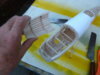
Some handy reference passed to me by a friend,ideal for the build.

P1050831.JPG

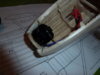
Trays of cut and sanded parts the results of quite a few hours fettling.

P1050832.JPG

P1050833.JPG

Does not look much at the moment but just wait and see what a delightful subject this will build into.

P1050834.JPG

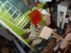
More parts ,the wing ribs.

P1050835.JPG
 
Thread owner
The build continues with laying down the keels and one side of the formers.

P1050852.JPG

The keels are joined carefully pinning them to the building board.

P1050855.JPG

Starting at the nose the half formers are carefully glued into place keeping them dead vertical.

P1050857.JPG

One by one and wetting the stringer that follows the nose contour the formers are glued into place.

P1050856.JPG

The lower wing support is fitted lining up with the lower slots of the formers.

P1050862.JPG

Starting with the four main fuselage formers these are then glued into place.

P1050865.JPG

Can you see the distinctive lines of the Hurricane emerging as we work on the fuselage ? it does not take much imagination.
 
Thread owner
Since the last pictures were taken the one half has been removed from the building board and today the formers for side two were added,these will be shown in the next set of build pictures.
I was hampered by former 5 which turned out to be wrongly shaped and the upper portion of the stringers did not meet up properly as it was not deep enough,some rectification filling has been done so that it matches up with the rest of the formers,these kind of things happen but its no big deal and easily rectified.

P1050869.JPG

P1050870.JPG

There will be no more building tonight dad this is a building board take over ! its nice and warm and I am by you.

P1050859.JPG
 
Thread owner
We are sailing along now with the fuselage and all stringers are in place,as the nose needs to take the motor this has been sheeted in between the stringers a time consuming task that took about a day to complete,everything has now been sanded and contoured around the nose area,next task is to cut mid way along the thrustline and vertically to make a removeable upper fuselage nose hatch portion,the battery box too will be in the nose area in another compartment.

P1050896.JPG

The completed internal planking all sanded to shape,the main undercarriage legs have been formed from music wire and these will shortly have balsa fairings shaped and added.

P1050871.JPG

Sacrificial horizontal pieces are added prior to glueing into place side two of the fuselage formers,small christmas tree pegs are useful for jobs like this.

P1050877.JPG

The formers and stringers for side two are now in place,the tail area has been pulled into shape at the sternpost.

P1050880.JPG

Main undercarriage legs fabricated from music wire.

P1050884.JPG

The start of the nose internal planking infills.

P1050887.JPG

Wedge shaped pieces are cut and glued into place,allowed to dry then trimmed off with a long blade then sanded with a glasspaper block.

P1050894.JPG

The area to the right of the nose planking mid point is for the centre section struts anchorage point.

P1050895.JPG
 

Attachments

  • P1050896.JPG
    P1050896.JPG
    3.3 KB · Views: 0
Thread owner
This mornings work on the Hawker Fury centered around the undercarriage main leg fairings which support the hefty internal suspension on the real aircraft,also the undercarriage attachments were improved,they just go into thin air on the plan as is usual with this kind of model,I use kits as a basis then improve on them vastly using tried and tested methods.
The supplied vac formerd wheels have good shape but are flimsy so I have made up balsa infills for them to add rigidity,once set the two halves will be joined together and a brass bearing inserted for the main axle.
The cockpit shape was made from stout cartridge paper.

P1050899.JPG

The undercarriage in place with balsa shaped fairings grooved and added,micropore tape helps hold them in place while cyno takes hold.

P1050900.JPG

The nose is ready for spackling then a good sanding.

P1050902.JPG

Cartridge paper cockpit shape.

P1050904.JPG

Vac formed wheels as supplied being strengthened with balsa discs glued internally then to be joined and bushed.

P1050905.JPG

The balsa discs sunk into the voids.
 
excellent stuff indeed fella,

looking forward to reading more as this progresses
 
Thread owner
A small video talking about these small scale radio model conversions.

 
Thread owner
Quite a bit of progress today centered around the wheels and removal of the front upper portion of the fuselage for access.

P1050917.JPG

The flimsy vac formed wheels have ben transformed into workable items,I did not want to discard them because the shape is very distinctive to the Hawker biplane stable,here we see them cleaned up after drying out overnight and brass tubing bushing pressed into the two halves,a skim of Squadron putty cleaned up the seams and a gentle sanding.

P1050919.JPG

To mask the wheel centres I rolled out some Whitetak and cut around a card telplate for the wheel centre,this was then placed onto the centre of the wheels and they were given a blast of matt black car rattle can paint.

P1050929.JPG

Then the wheel centres were painted with some silver Humbrol I had in my paint stash.

P1050922.JPG

With a razor saw I removed the upper front portion of the fuselage,after some work this will accomodate the motor bulkhead at F2,behind that will go the ESC speed controller and the battery will sit somewhere in the cowl in its own battery box,but we are not quite ready to fit the bulkhead etc as something very important has to be done next,with a mixture of balsa dust and Aliphatic adhesive a balsa paste is made up,this is then painted all inside the exposed nose area between the balsa infills and stringers,this has the effect of consolidating everything,its very light but strong,I have developed this technique over the past few years and it makes for a very sturdy front end and you can cut/saw and add things to it,overnight it settles and sinks into every crevice setting hard,yes its a lot of extra work but well worth the extra effort.

P1050927.JPG

Balsa dust is stirred into the Aliphatic glue with an artists palet knife,a stiff paint brush is used to push it into every corner.

P1050926.JPG

Not a pretty sight but overnight it will settle out and become very much part of the nose structure,being made from balsa dust it is very light as evaporation takes place.

P1050928.JPG


The nose area just prior to treatment with the balsa paste,weight is nearly always needed around the nose so why not use it in the structure rather than adding useless ballast such as lead ?

P1050921.JPG

Another view of the nose area just after cutting showing all the balsa infills between the stringers.
 

Attachments

  • P1050922.JPG
    P1050922.JPG
    3 KB · Views: 0
Thread owner
Time to fit the small outrunner motor so everything else can be worked out around it,firstly a small ply bulkhead is made up and the motor bolted into place,then it is positioned so it gives 3 degrees right thrust to compensate for the torque of the motor pulling to the left,a few degrees of down thrust is also added.
The assembly is then carefully spot glued into place and a fillet of balsa paste is formed around the bulkhead,this locks everything including those important thrustlines into place.

P1050932.JPG


P1050934.JPG

The small bore brass tubing for the cabane strut attachments is installed into the fuselage,the kit simply glues the struts to the sides but we can do better than that and make a neater more workmanlike job.
 

Attachments

  • P1050930.JPG
    P1050930.JPG
    2.5 KB · Views: 0
Great thread. I'm particularly interested as I'm just coming to the end of my own Fury build, well ok, not quite the same, mine's a touch smaller and plastic.
 
Thread owner
The work on the Hawker Fury today centers around starting to make the tail surfaces and adding a bit of cockpit detail,here we go....

P1050935.JPG

We can use the kit parts to make the tail frames but these will have 1/32nd balsa cladding and hinged with additional spars in place for our small powered flying model,the hinges are simply cloth trapped between layers one and two,first the cladding is bevelled at the leading edge then glued into place and when everything is dry cut apart the the other side is positioned.

P1050936.JPG

One side of the cladding has been added in this picture.

P1050939.JPG

First side prior to adding the cloth hinge,simple and effective.

P1050942.JPG

The trapped cloth hinge in place,next job to add side two.

P1050940.JPG

Sanded with hinge line visible,all ready for control horn in the next picture.

P1050948.JPG

Simple,clean and effective,time proven too.

P1050945.JPG

The wing centre section and tailplane are laid down onto the board,once again these will be heavily modified and the parts used as a guide to the modifications for our model.

P1050950.JPG

A bit of simple cockpit detail,first a coat of Dulux tester paint 'Enchanted Eden' spot on for cockpit green,my friend scaled down a real instrument panel for me and printed it out,this was stuck to cereal box card and glued into place,seat was cereal box card folded,wood stick has spade grips to be fitted still.

P1050949.JPG


P1050951.JPG

You cannot beat a bit of Dulux.
 
Thread owner
Moving on to sort out the cabane centre section and allied strutting,the only real way to do a biplane centre section is to prepare simple sacraficial jigging,the jig is placed around the area of the fuselage and parts built around it giving the exact wing incidence and rigging decalarge,the Fury has 2 degrees of upper wing incidence,this enables the top wing to stall first before the lower wing normally the case on most biplanes,the lower wing is rigged neautral with the tailplane but can normally in the case of the real machine be altered on the ground to make the aeroplane fly nose heavy or tail heavy depending on the machine and how it handles,even same types of aircraft will fly in a different way.
The lower brass tubes that were installed previously pick up the front and rear cabane struts,I have initially used piano wire which will be faced with balsa streamlining,once everything has been set up and in place the jigging is discarded after taking apart.

P1050957.JPG

First a wing platform shape is determined and tacked into place.

P1050959.JPG

The centre section is temporarily screwed to the incidence platform,everything must be dead true and square making small adjustments.

P1050965.JPG

The forard wire struts are bent and added to the jigging locking in place,put aside to dry at this stage before proceeding.

P1050958.JPG

While this was glueing up I did some more work on the tailplane and elevators.

P1050955.JPG

After sheeting one side I added the brass elevator joiner and installed the cloth hinge membrane ready to receive the upper skinning trapping the hinge at the same time.

P1050953.JPG

The centre section receiving its lower skin before the jigging operation.
 
Thread owner
And showing the strut wires in place plus the addition of a wooden forward facing strut in between soon all will be faced with wood as well,the wire is for strength and the wooden streamlining for scale effect.
The jigging you see below the wing centre section is torn away when everything is in place.

P1050967.JPG

P1050969.JPG
 
Thread owner
With the cabane strut wood pieces now added and the tail assembly ready for installation here are some more pictures from the workbench today.

P1050976.JPG

P1050974.JPG

P1050975.JPG

And some bonus items ,the Hawker Fury has nearby friends under restoration and under build.

P1050980.JPG

The Bristol Beaufghter undergoing restoration.

P1050984.JPG

Gradually coming together again.

P1050983.JPG

The B-24 new wiring looms being made up,with Shorts Stirling below undergoing a rebuild.
 
Thread owner
A morning spent fettling the wings and making adjustments to the wing fitting areas,the wingtips have been fitted with depron infills so these can be sanded to the contours of the wings,nice and light and a good base for where the tissue covering goes.

P1050992.JPG

P1050993.JPG
 

Attachments

  • P1050991.JPG
    P1050991.JPG
    3.8 KB · Views: 0
Thread owner
Wings have all been cleaned up,tips shaped and the Fury rigged up with weights and wood jigging pieces,as you can see upper wings are in place and glued,the model will not be touched but left to dry until tomorrow when the the lower wings can be fitted,it is a tricky job best done in stages.
Lower surfaces of upper wings and upper surfaces of lower wings were first covered in tissue,the reason for this will become clear later on in the assembly.
A lot of model building is about pre planning things like this important stage of construction.

P1050998.JPG

P1050999.JPG

P1050997.JPG

wings covered in Jap tissue,see how nice and smooth the wingtips are with the depron addition which was pre shaped and sanded before covering,at this stage the tissue is just shrunk with water,doping will happen later.
 
Nice work. It's a bit of a daft thing to say/type, but I really like the way your build mimics the real thing in the way of construction.
 
Status
Not open for further replies.
Back
Top