Theme editor

Scale Model Shop

Hemingway Kits Knurling Tool

Mr Bowcat

SMF Supporter
Joined
Dec 29, 2016
Messages
4,736
Reaction score
225
Points
63
Location
London
1/3
Thread owner
Morning all,

So I've had my mill for a few months now, the lathe I've had around 4 years. Since I've had the mill I've been busy learning how to use it and decided it was time to actually build something useful. Hemingway supply kits to model engineers, including engines and locomotives, but also sell a number of tooling projects. I already have a purchased knurling tool, but it's not very good, and this clamping style that I'm building should work a lot better.

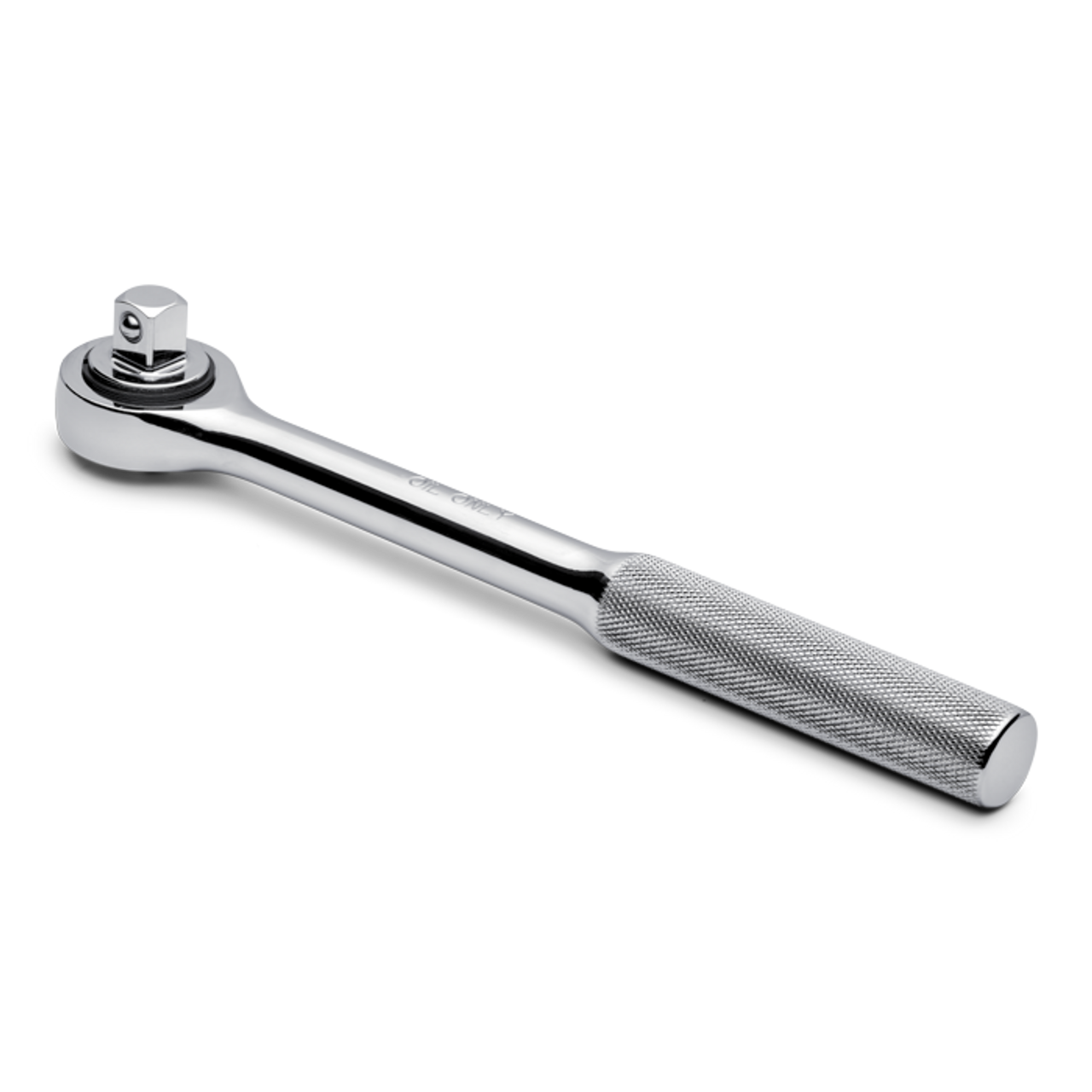
For anyone who doesn't know knurling is the imprinted pattern often found on tool handles, like this:

4426-a__98510.1705057584.png


On to the kit, the box art:

54049181238_9037f00297_c.jpg


The instructions:

54049259204_d41026071f_c.jpg


The sprues: 😂

54049259179_f6d12227f3_c.jpg


I spent some time on the instructions, this is the first time I've used proper engineering drawings and it took some time to decipher them, particularly as they are in Imperial and I work in Metric.

The first step is the main body, which are the side plates and a spacer block. All parts were machined to dimension, and a number of holes drilled, and in some cases tapped. Two further holes were drilled and reamed to precise dimension which will later take the arm pivots. The rear corners were also knocked off, this will be the operator side so lessens the chance of injury.

54048068402_2c17a83fb0_c.jpg

54048068447_ce3ff854bc_c.jpg


The final step to this part is the tool block, this is simply an extension to allow the tool to be mounted to the tool post.

54048928211_6042cce021_c.jpg

54048928301_3501c582e4_c.jpg


And that little lot took around 6 hours! What I have learned from machining is that most of the time is spent fixturing and measuring, and a small amount actually drilling or cutting.

I am very pleased with the progress however, everything fit perfectly, and is square and true and all the holes lined up perfectly, so I'm doing something right.

Next up are the arms which are far more complex pieces with a number of features to be machined.
 
Thanks for sharing the project, I really love these kind of projects and machining and all that, I'm more of a woodworker myself, but if I had the budget and know-how I would get metal machines as well. Have fun, cheers
 
Thread owner
Thanks Steven,

Know how has just been picked up from books, forums and You Tube (and plenty of practice), but if I could go back 30 years I think an apprenticeship and career in engineering would have been fun.

The machines aren't cheap, mine are bench top "hobby" models, but still a bit spendy. Saying that, I actually bought the mill in April because it had 25% off (around £500 saving) but at the time didn't actually have space for it. it wasn't until around July that I had cleared space in my workshop (which involved having a concrete slab poured and building a new, much larger shed for all the stuff that was in the workshop) that I could use it. 😂
 
Very interesting. Looks as if you've certainly got the hang of this engineering. I look forward to future projects.
 
Thread owner
Cheers Jim. :)

It's early days but I'm learning all the time, and as Adam Savage says, chasing zero's.
 
Cool. Not a touch envious. I would love a lathe and a mill.
Maybe one day a Proxxon thing will land my way.
 
Very cool project! I have been a machinist for basically my whole working life.
 
Thread owner
Morning all. :)

I've been out in the workshop the last few evenings working on the arms. The first steps were just to machine to dimension and drop a couple of holes in each arm, one for the pivot to the main body, and the other for the knurling wheels.

While everything was still square I decided to tackle a feature that I wasn't looking forward to, a shallow scallop in each arm.


54059143025_a22a3b3009_c.jpg


This would be easy to do on the milling machine with either a rotary table or boring head, unfortunately I have neither. I had a good think about it and decided the only way I could do this was on the lathe with a boring bar, the issue being how to fixture the parts. I think I came up with an elegant solution.

54058929793_d47898c084_c.jpg

54059011569_2affd4b58e_c.jpg

I milled some 10mm plate and used the existing holes in the arms to attach them to the plate. I also added a centre drill hole in the middle to allow the part to be dialled in precisely.

Centre drills form a 60 degree cone for the purpose of adding a live- or dead- centre for support. For my purposes by adding an extension between my live centre and the work piece in the chuck I could dial in on the extension to get everything centred. Better still, I managed to get it to within 0.005mm (5/1000 of a millimetre), or about 2 ten thousandths of an inch.

54059137345_a137e78c40_c.jpg

54059011554_088079d8e3_c.jpg


A quick scratch pass with the boring bar showed I was dead nuts on, now all I have to do is remove the material.
 
So do you say "Aaaannnnnd Yahtzee!" when you part bits off. IYKYK
 
Looking at those dimensions and angles, that's quite a big challenge to set up 👨‍🏭 Hope it turned out well
 
A very clever solution. Hope it works. You're learning all the time.
​​​
 
Thread owner
No, I think Quinn has that copyrighted. :D

Seriously though, parting off is my least favourite activity, on a small lathe it's a fine balance between feeding in fast enough, but not so fast that you jam the parting blade and stall the machine.
 
Thread owner
Cheers gents. :)

Well the boring went quite well, surface finish could be better but should clean up with some emery. To be honest it's not too critical, there will be some brass parts riding in the scallops but they won't be high friction.

54066117200_23f332f744_c.jpg

54064787707_758e952ae5_c.jpg


With that done and the edges tidied up with a small file the parts were taken to final dimension and a slot milled through each one. This was a little tricky as the slots are angled out at 10 degrees each end.

54066117180_2e3c271638_c.jpg

54065983099_dfe92b30d4_c.jpg


Last couple of operations for the arms are the slots for the knurling wheels, but before that the radii need adding to each end of the arms. Again, this would be an easy job with a rotary table, but I don't have one. I could just grind in the radii with a belt sander, the actual curves are not too critical, but I wanted to try and do better. With this in mind I turned to an old school technique and made some filing buttons.

Essentially these are turned from steel to the required diameter and a hole drilled through the middle the same size as the holes in the part. These are then bolted through on either side of the part and act as a guide for filing the curve. The clever bit is that they are made from O1 tool steel which is heat treatable, so after heating to around 800C they are quenched in oil and come out glass hard, meaning the file will skate over them.

54065983074_eba67f151c_c.jpg

54066117160_060a87f8ab_c.jpg


I will remove most of the material on the mill first, then just file down to the buttons, hopefully leaving a perfect curve.
 
That looks the part 👍 nice work and good thinking with the heat treatable parts, cheers
 
Thread owner
Morning all.

Just a quick update, I took most of the unwanted material off on the mill, then hand filed down to the buttons.

54069834407_516e50d165_c.jpg

54071169050_35345fc901_c.jpg


The buttons worked perfectly. I did have to stone the sides a little, the sections where I had milled the slots were a little tight in the main body, I will clean these up with sandpaper before final assembly.
 
Thread owner
Morning all.

Getting close to the end of this now, finished some more parts over the weekend.

I started with the pins for the arms and knurling wheels, these were turned from 1/4" drill rod, with the two for the knurling wheels tapped through for M3 hex bolts. These still need to be heat treated before final assembly.

54082540234_41dbb5940d_c.jpg


I then moved on to the parts that ride in the scallops machined in to the arms earlier. This starts of as round bar and has a 5mm hole drilled through. The middle was then milled out and one hole opened up to 1/4", the other tapped for M6. The stock was then put in the lathe and the two parts parted off.

54082540179_7a29ced0dd_c.jpg

54082464143_6a7562bdc5_c.jpg

54082673450_1da8b8156e_c.jpg


The last part of this weekend was the leadscrew which is just 1/4" rod, turned down to 6mm in a couple of sections and threaded M6.

54082673545_54516888ed_c.jpg


And this is how it looks now. What cant be seen is a spring between the two arms that goes around the lead screw. When the nut is tightened the spring allows the arms to move together the same amount and the scallop parts allow everything to move without binding. The nut is just temporary as the next part is the adjustment knob, but the tool will function in it's current form.

54082540269_110d12d998_c.jpg
 
I had access to various lathes in previous jobs, culminating in a very nice Myford Super 7 with the Tri-Leva speed selector and screwcutting gearbox. I supplied a local model shop with small parts and made some special tools for the local car club. One thing I could never get to work though was knurling, so I'm hoping you have more success.
Pete
 
Back
Top