
You are using an out of date browser. It may not display this or other websites correctly.
You should upgrade or use an alternative browser.
You should upgrade or use an alternative browser.
SE5a CONSTRUCTION BEGINNING TO . . .
- Thread starter Greyhead
- Start date
- Status
- Not open for further replies.
Alan
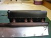
The “rusty pitted” surface is created by the 5 minute epoxy / micro balloon mixture. It’s spread thinly over the entire surface, where more pitting is required leave a slightly thicker layer and keep dabbing it as it cures, I use my finger for this but that’s probably not to be recommended!
Grahame
To finish the effect use matt black, rust (Humbrol 113) and mixtures of both and dry brush until you’re happy with the result.
View attachment 262792
I find the best brush to use for this is one with short, fairly stiff hairs and to use progressively drier coats. By finishing off with a virtually completely dry brush the matt black develops a slight sheen so characteristic of exhausts.
Attachments
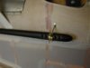
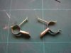
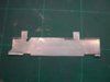
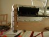
When it came to actually making the rear brackets I decided against my original idea and made the strap hinged; I used a thin mylar strip epoxied to the inside of the strap. The brackets are attached to the fuselage by a 14BA bolt through the top flange; I don’t want to drill the longerons so the bottom flange is just held with epoxy, which will be further strengthened by covering with frayed tape.
View attachment 262793
The pinch bolt would have held the bracket together on its own but the mylar is a bit of “belt and braces” and it will also make sure that there’s no “metal to metal” contact between the bracket and the litho plate end of the exhaust pipe.
View attachment 262794
View attachment 262793
The pinch bolt would have held the bracket together on its own but the mylar is a bit of “belt and braces” and it will also make sure that there’s no “metal to metal” contact between the bracket and the litho plate end of the exhaust pipe.
View attachment 262794
Attachments
I’ve never been entirely satisfied with the original radiator grill and have been looking around for an alternative; unfortunately I’ve not found any cheap DIY type material so have had to resort to buying some etched brass.
The result is a lot more realistic, it’s not true hexagon but it is about the correct size and being so small it certainly looks right. From the right-hand picture you can judge just how small the holes are.
View attachment 105998
I bought the brass from EMA Model Supplies:
http://www.ema-models.co.uk/
View attachment 219021
Attachments
G
Guest
Guest
Will your SE5a have those louvred slats over the radiator grills ? Those would look great in litho plate!
I've seen some models where they open and close according to throttle position too.
I've seen some models where they open and close according to throttle position too.
It’ll certainly have the radiator slats and they’ll certainly be open, no point spending all that money on etched brass and then covering it up!
Making them move would be too complex / unreliable at this scale, at least it would for me.
Making them move would be too complex / unreliable at this scale, at least it would for me.
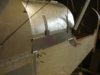
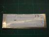
The tank cover side extensions are quite a complicated shape so it makes sense to use a template for cutting the litho plate but taking measurements from the model can be awkward, there always seems to be something that stops you getting the rule in the place you want!
A template is drawn as accurately as possible then scanned into the computer and several copies printed out. Cut one out first and check the fit; if it ‘s OK first time all well and good but most likely you’ll have to adjust the other templates as required, this one needed the front “tab” moving slightly forwards.
View attachment 262821
Selotape the template to the litho plate and cut out, it cuts easily with a scalpel but the blade won’t be much good for cutting balsa afterwards.
The false hinges are made as described in an earlier post.
View attachment 262822
Once glued in position the hinges show up very well and really add to the “realism factor”.
View attachment 262823
Attachments
Now I’ve got the job of making 60 radiator slats!
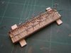
First I made one to check the principle but measuring, cutting and bending another 59 as individual items is not really an option because the chances are that there would be noticeable variations so I’ve made a jig. It’s simply a piece of 1mm brass bent to shape with some 0.5mm steel soldered to it to produce a slot 1.5mm deep and twice the thickness of litho plate wide.
View attachment 105837
The litho plate was cut into 26mm wide strips, the end folded back onto its self then placed in the jig and one flap folded down forming one half of the slat.
View attachment 105838
The slat was cut from the strip and the process repeated until I got bored, which was after about 20, I then cut the pins to length and “tacked” them in position with a drop of cyano. The flaps were given a thin coat of epoxy, the whole lot put back into the jig and the litho plate bent around the pin.
View attachment 105839
Once all the slats are at this stage I will modify the jig to enable the other half of the slat to be cut consistently at 1.5mm.
EDIT: This method of producing the radiator slats has proved to be unsatisfactory; see this post.
View attachment 218860
View attachment 218861
View attachment 218862
Attachments
G
Guest
Guest
I know the feeling with making the repetitive parts, not so much fun but well worth the end result.
I did a similar thing with My HMS Active that I built. The four Exocet containers all had ribs on them. I did the ribs on all 4 containers. 144 ribs in total...not much fun at all, but they certainly look the part now.
Keep the good work coming Grahame, I am really loving seeing it come together now.
Regards......Mark.
G
Guest
Guest
I envy your skill and paitence Grahame.:bravo:
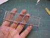
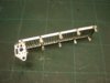
It’s been a tedious, that’s not to say boring, few days but I now have the 60 radiator slats I need. The slats, 30 for each radiator, have to be accurately positioned so are held in a jig whilst being soldered to the sidebars; the pins keep all the slats at the same angle.
View attachment 262833
The soldered joints are tidied up with the Dremmel then the lot epoxied to the frame, which is made from litho plate; the railway track pins will be used to attach the finished frame to the brackets that hold the unit to the radiator.
View attachment 262834
View attachment 262833
The soldered joints are tidied up with the Dremmel then the lot epoxied to the frame, which is made from litho plate; the railway track pins will be used to attach the finished frame to the brackets that hold the unit to the radiator.
View attachment 262834
Attachments
G
Guest
Guest
Brilliant work Grahame!
It was really worth taking the extra effort to make those individual slats - they look great!
It was really worth taking the extra effort to make those individual slats - they look great!
Before fixing the radiator slats to the fuselage all that needed to be done was to solder the brackets to the track pins; a simple job or so I thought!
View attachment 262835
This is where I hit another problem; my “new” supply of track pins won’t solder, they must be made from a different metal. Of course for their intended use in model railways it doesn’t matter whether or not they’re solderable so I can’t really complain.
Anyway it was quite a job removing them without damaging the litho plate so it’s taken all day just to get one side to this stage; I should have checked before gluing them in place but I never gave it thought!
Attachments
After much delay my 5” Williams Brothers Vintage wheels have arrived; although they are not in their catalogue DB Sport & Scale ordered them from America especially for me at no extra cost, excellent service!
In the past I’ve used Williams Brothers wheels and although they are quite expensive I considered them to be good “value for money” because of the quality and detail of the moulding. As I’m sure you know they recently went out of business, someone else now produces the wheels, and I have to say I’m rather disappointed with the result.
There has been some damage to the mould and because the surface is textured to represent the fabric covering, it will be difficult to remove the blemish without it being obvious. Also the valve detail is poor; it looks as if this is a produced by a separate insert in the mould, perhaps the original has got lost and been replaced with an inferior version.
My idea at the moment is to use Solartex to make a cover, if it works it may well look even better than an “original” Williams Brothers wheel but it’s a job I could have done without.
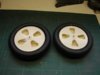
On to happier things!! Having sorted the method, the second radiator frame went a lot easier than the first and although it’s been quite a fiddly sort of job I’m really pleased with the end result.
View attachment 262837
When everything’s painted PC10 except for the slats themselves they should make quite a “feature” on the front end.
View attachment 262838
In the past I’ve used Williams Brothers wheels and although they are quite expensive I considered them to be good “value for money” because of the quality and detail of the moulding. As I’m sure you know they recently went out of business, someone else now produces the wheels, and I have to say I’m rather disappointed with the result.
There has been some damage to the mould and because the surface is textured to represent the fabric covering, it will be difficult to remove the blemish without it being obvious. Also the valve detail is poor; it looks as if this is a produced by a separate insert in the mould, perhaps the original has got lost and been replaced with an inferior version.
My idea at the moment is to use Solartex to make a cover, if it works it may well look even better than an “original” Williams Brothers wheel but it’s a job I could have done without.
On to happier things!! Having sorted the method, the second radiator frame went a lot easier than the first and although it’s been quite a fiddly sort of job I’m really pleased with the end result.
View attachment 262837
When everything’s painted PC10 except for the slats themselves they should make quite a “feature” on the front end.
View attachment 262838
Attachments
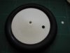
I’ve decided that something has to be done with the wheels. One thing that everybody seems to complain about with Williams Brothers wheels is the weight; they are heavy but in the past I’ve been prepared to put up with it because of the quality. Having “attacked” the wheels it’s obvious why they’re so heavy, the plastic mouldings are a good 3mm thick, so removing ½ the back is a considerable weight saving exercise in it’s own right.
I started with the back face for a couple of reasons; firstly, if it turned out to be a complete disaster any repairs would be less on show and secondly it lets me see the internal structure. In fact there is very little internally, the two sides are simply joined at the hub and the outer rim so there will be no problem drilling the “valve hole”.
View attachment 262839
A word of caution; if anybody thinks this is a good idea and is thinking of doing the same I’d wait a while, I’ve never tried this before and could well end up with £20.50 worth of rubbish so I’d wait and see what the end result actually is!
Attachments
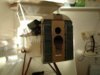
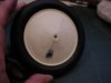
The front face of the wheels has the area between the spokes where the valve hole will be removed, I also reduced the length of the “spokes” as I prefer the look of the wheels where only the first section of the spokes shows through the fabric covering. Before applying the Solartex the surface is wiped over with thinners to remove any residue of mould release agent and given a coat of Clearcoat.
First I tried to cover in one piece, shrinking the outer edge to make the “cone” shape; there was enough shrinkage to take up the correct shape but it proved impossible to get it even. I eventually cut the disc of Solartex along a radius opposite the valve hole, bonded it around the outer edge and cut off the excess then worked towards the centre using the iron
View attachment 262840
It took me 4 attempts before I got the method right but the finished wheels look just right; not perfect, the “faults” are now as they should be, small creases in the fabric (not obvious moulding faults). The valve hole doesn’t look round in the photo but that’s just the matt black paint, which I’ve painted the insides of the wheels with.
Attachments
G
Guest
Guest
The wheels look much better with the covering stretched over the spokes in the centre of the wheel but not at the edges, gives a much better scale look.
How were those original wheel covers attached to the aircraft? I noticed on the wheel there are some obviously modelled on protruberances around the rim, were these stitches or some kind of eyelet and a wire fastener or something?
The only reference I could find was here:
http://www.hawker-restorations-ltd.co.uk/Media/Avro/8.html
Palmer Detachable Wheel Shield from a 504
Yes the covers were laced with beeswax cord binding,mud was a problem especially operating from rough grass fields,the wheels and bearings needed constant attention and the covers became very grubby and worn looking.
Also the springing from these wheels was poor due to the narrow rims and Palmer tyres ,the rubber bungee lashings was the only suspension.
Also the springing from these wheels was poor due to the narrow rims and Palmer tyres ,the rubber bungee lashings was the only suspension.
Alan
There are various methods of lacing the wheel covers; the one used on the Williams Brothers wheels is a kind of zig-zag stitch similar to the fuselage stitching, there was also a “running stitch” which follows the diameter and probably several more methods that I don’t know about! There are also the ones that apparently don’t have any lacing, at least none that shows, whether or not they use clips I’ve no idea; as far as I’m aware this method was used for the SE5a, on the C1096 restoration there is no rim showing at all.
Whether the spokes show only near the hub or right to the rim depends on the position of lacing and the way the spokes are arranged, if the wheels have the spokes arranged radially then they are more likely to show right to the rim, if they are crossed over, like bicycle wheels, more likely to show just near the hub but it’s really a combination of the two things.
Grahame
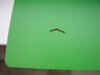
The valves are made from lengths of 2mm brass tube with the ends threaded.
View attachment 262841
The valves are heated up then “melted” into the rims so the ends show through the valve holes; just the back to cover now, that’ll be no problem as they are virtually flat discs.
View attachment 262842
There are various methods of lacing the wheel covers; the one used on the Williams Brothers wheels is a kind of zig-zag stitch similar to the fuselage stitching, there was also a “running stitch” which follows the diameter and probably several more methods that I don’t know about! There are also the ones that apparently don’t have any lacing, at least none that shows, whether or not they use clips I’ve no idea; as far as I’m aware this method was used for the SE5a, on the C1096 restoration there is no rim showing at all.
Whether the spokes show only near the hub or right to the rim depends on the position of lacing and the way the spokes are arranged, if the wheels have the spokes arranged radially then they are more likely to show right to the rim, if they are crossed over, like bicycle wheels, more likely to show just near the hub but it’s really a combination of the two things.
Grahame
The valves are made from lengths of 2mm brass tube with the ends threaded.
View attachment 262841
The valves are heated up then “melted” into the rims so the ends show through the valve holes; just the back to cover now, that’ll be no problem as they are virtually flat discs.
View attachment 262842
Attachments
- Status
- Not open for further replies.
Legal Notice
scalemodelling.co.uk is a privately operated online discussion forum. All content posted by members reflects their own views and opinions and does not necessarily represent those of the forum owners or administrators. While reasonable efforts are made to moderate content, no responsibility is accepted for user-generated material. By using this site, you agree to comply with UK law and the forum rules.