Theme editor

Scale Model Shop

SE5a CONSTRUCTION BEGINNING TO . . .

Status
Not open for further replies.
Thread owner
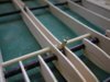
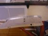
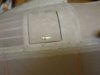
The flying wire attachments are fixed to the spars by epoxy and binding with button thread; I didn’t want to compromise the spars by drilling holes at these high stress points. For some unknown reason the inner and outer brackets are of completely different designs.


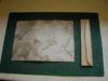
The inner is bent from thin brass sheet.


View attachment 262880


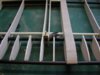
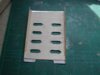
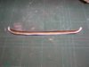
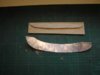
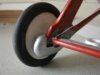
The outer is from 0.5 mm steel.


View attachment 262881


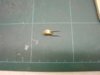
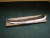
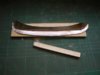
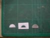
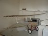
Next to the bracket is the fixing for the inter plane strut and once again it’s a closed loop adaptor! They will enable some fine adjustments to the lengths of the struts and also allow a degree of “span-wise” movement between the top and bottom wing halves, which I think is advisable as they will be permanently joined by the struts, it should help when sliding the wings / fixing rods into position on the centre section.


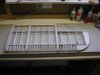
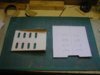
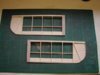
One wing finished, now I’ve got to repeat the exercise another 3 times!


View attachment 262882


To alleviate the boredom I’ll do a bit more detailing to the fuselage in between!
 

Attachments

  • wing 15.jpg
    wing 15.jpg
    3 KB · Views: 0
  • wing 16.jpg
    wing 16.jpg
    2.4 KB · Views: 0
  • wing 14.jpg
    wing 14.jpg
    2.7 KB · Views: 0
Hi Grahame. Great job! And thanks for sharing your work with us. How are you hinging the ailerons? I used carbon fiber tubes for my spars, but switched to balsa at the ailerons. I couldn't figure a way to hinge with the carbon fiber.

Steve

 
Thread owner
Steve


The aileron hinges will be the same as I’ve used for the rudder and elevators, both of which use carbon fibre tubes.


The hinges consist of a brass yoke with a brass tube soldered to it and a piano wire hinge pin.


View attachment 262883


The yoke goes over the carbon fibre tube and has a retaining pin fitted through the 2 holes to prevent the hinge being pulled out, the piano wire hinge pin has a brass keeper soldered behind the control surface leading edge for the same reason.


Grahame
 

Attachments

  • hinge 1.jpg
    hinge 1.jpg
    1.6 KB · Views: 0
Grahame, Thanks for the info. It's always amazing to see how many ways there are to skin a cat.

Steve
 
Thread owner
I have recently received some research material from a fellow SE5a modeller and it has raised a query about the dihedral angle. To save me writing it again, here is a copy of an email I sent:

I've now read the articles you sent me and there is lots of very useful information in them; thanks again.

One thing that is a bit of a cause for concern is the dihedral angle. I'd read several references on the Internet to the angle being 5º and sometimes being reduced by 1º or 2º in the field; I had assumed this was correct because it was confirmed from different sources.

In one of the articles you sent me it says the dihedral angle is 3º 20’; this is very precise if it’s a “guesstimation” so I assume that this is the true angle obtained from factory drawings. Some modifications to my model would appear to be in order; luckily it’s not too late, the wing rods haven't yet been permanently fixed.

To make matters worse I've repeated the 5º angle in my posts in your thread, as well as my own, so that would appear to anyone searching the Internet to be extra corroboration from myself. I'll have to edit the posts to include this “new” information.

Just goes to show that you shouldn't believe all you read on the Internet!
 
Hi Grahame. I agree with your statement. Don't believe the 3deg article either unless it can be backed up from other sources. I have six different sets of three and five views. They all show 5 deg dihedral. Also I have it in writing in two publications ( WWI Areo and Squadron/Signal). Different field mods were made to just about everything on this plane, but unless you know that the plane you're modeling had a different dihedral, I'd stick with the factory 5 deg

Steve
 
Thread owner
I did a temporary rig of the top wings using both 5º and about 3.3º and to be perfectly honest I really couldn’t tell the difference when looking at the model as a whole so I’ve decided to stick with the 5º that I originally built in to the mounting blocks; anything for an easy life!

Out of interest Steve do your drawings have the 5º angle written on or have you measured it with a protractor?
 
Hello Grahame,

that was quite a job to read all the post since my last visit to scale models. But once again I was highly impressed. The photographs in addition to your comments show that it's always worthy to think (and make) over every single detail till you're satisfied with the result. Great job.

Greets from Germany,

Dirk.
 
Hi Grahame. WWI Areo Publishers lists 5 deg dihedral in the specs. The drawings I have are scanned into a CAD program on my PC. I draw a line from tip to tip and then along eachleading edge. The program gives the angle anywhere from 4.8 to 5.1 for the six front views that I've checked.

Steve
 
Hi Grahame

Ive just come across this thread whilst looking for info prior to building a DB sport and scale kit at 1/3 scale.

All I can say is you have really inspired me AND given me all the scale info I need.

Keep it going!!!
 
Thread owner
Squarehead


Glad you’ve found the thread useful; any specific questions just ask and I’ll do my best to help.


Grahame


Both top wings are complete and ready for the ailerons, so before I start on the bottom wings I decided to have a change and go back to the fuselage and build the under pan.


Some SE5a’s had louvers and some had holes; to aid cooling I’ve gone for the latter. It’s very important to have ample escape routes for the hot air; I aim for twice as much as the cooling air that enters the cowl. Here the under pan, made from 1/32nd ply is ready be covered with litho plate, which has been marked out ready for the “rivets” to be embossed.


View attachment 262884


The litho plate will be glued to the ply before the holes are cut out.


View attachment 262885


The litho plate is unsupported at the rear because it has to extend back further than the ply backing, for this reason the litho plate is best used non-annealed. Because there are only the 2 side bends and no compound curves the litho plate is still workable in this state.


View attachment 262886


The finished under pan in position; just the attachment “hinges” to be fitted but as these are quite delicate I’ll leave them till much later in the build.


View attachment 262887
 

Attachments

  • cowl 38.jpg
    cowl 38.jpg
    2.6 KB · Views: 0
  • cowl 37.jpg
    cowl 37.jpg
    2.1 KB · Views: 0
  • cowl 36.jpg
    cowl 36.jpg
    1.6 KB · Views: 0
  • cowl 35.jpg
    cowl 35.jpg
    2.4 KB · Views: 0
Thread owner
With the top wings fitted I confirmed the positions of the flying wires where they pass through the lower wing stubs, built in the guides and covered them. Where the wing stubs join the fuselage there is a metal cover riveted to the wing and the front section to the fuselage, the rear section is laced to the fuselage fabric.


When forming litho plate it is sometimes easier to make a former rather than use the model and this is what I decided to do this time. There is a lot of forming to be gone so the litho plate is annealed; the photo shows the effect you get after annealing, the soap has turned very dark brown, nearly black in places.


View attachment 262888


A “generous” blank is cut; it does help to follow the shape to some degree.


View attachment 262889


Start the forming using a piece of suitably sized soft balsa until it gets to this sort of stage.


View attachment 262890


The excess litho plate should now be cut away to allow the final shaping; here the front has been completed.


View attachment 262891


When all the shaping has been done the part can be finally trimmed to the finished size.


View attachment 262892


Rivets are embossed using an old ballpoint pen and the lacing holes punched out with a pin. The cover is laced very loosely, glue applied to the faces and the lacing gradually tightened as the cover is manoeuvred into position.


View attachment 262893
 

Attachments

  • wing stubs 11.jpg
    wing stubs 11.jpg
    2.1 KB · Views: 0
  • wing stubs 10.jpg
    wing stubs 10.jpg
    1.7 KB · Views: 0
  • wing stubs 9.jpg
    wing stubs 9.jpg
    1.9 KB · Views: 0
  • wing stubs 8.jpg
    wing stubs 8.jpg
    1.8 KB · Views: 0
  • wing stubs 7.jpg
    wing stubs 7.jpg
    1.8 KB · Views: 0
  • wing stubs 6.jpg
    wing stubs 6.jpg
    2.1 KB · Views: 0
A pleasure to see something take shape as always and, once again, using basic techniques and traditional materials.

Lovely job Grahame
 
Thread owner
I thought I deserved an easy weekend so it’s on with the top ailerons. As with all things SE5a there are some complications but they are for later, for now it’s just good old “balsa bashing”, very therapeutic!


View attachment 262894
 

Attachments

  • wing 17.jpg
    wing 17.jpg
    2.4 KB · Views: 0
Thread owner
As I’m going to sunnier climes for a week tomorrow I didn’t want to start on anything major today so looked around for some simple detailing.


First the luggage hatch. all that was needed was to cover the section previously remove with Solartex, add a couple of litho plate hinges and a brass fastener.


View attachment 262895


On this model there is no point in making the hatch openable so the hinges and catch are imitation and the hatch itself is simply glued in position.


Next the steps, being an SE5a they aren’t just holes cut into the fuselage sides as most WW1 planes used, they have a hinged flap that is pushed out of the way by the pilots foot, the flap then closes to fill the hole; this has definite advantages and disadvantages for modelling. The advantage is that there is no need to weaken the fuselage by cutting a hole in the fuselage in an area that is already compromised by the cockpit cut out, the disadvantage is that it is a more complicated build!


I used 2 layers of litho plate. First the “flap” is cut out then the “hole” with a generous surround, the rivets are embossed and the 2 halves glued together and the litho plate formed around the “flap” to give it some depth before finally filing to size.


View attachment 262896


To cut the arc of the hole the easiest way is to form a close “perforated” line using the point of the scalpel before cutting along the line again with the pointed scalpel, then tidy up with a file.


At this point I have to say that these are not the steps I’ll be using! I had previously drawn the shape to scale and stored it on the computer until it would be required. Today I printed them out onto sticky labels and got to work. When I glued them in place and sat back to admire my handiwork I thought, “WW1 pilots must have had dainty little feet to use them steps!!” A quick check on the size showed that they were in fact only 63% of the required size. Although this has never happened before for some reason the computer had resized the drawing to fit the labels and I hadn’t noticed! The moral is measure twice and cut once.
 

Attachments

  • steps 1.jpg
    steps 1.jpg
    1.8 KB · Views: 0
  • decking 18.jpg
    decking 18.jpg
    1.6 KB · Views: 0
Thread owner
Now back in England and missing the sun, but I have to admit that I did suffer from “withdrawal symptoms” whilst abroad not having my daily fix of “shed time”!!


I’ve made new steps, this time the correct size, no point posting a photo as they look the same as the first ones, just bigger!


One of the rubber “O” rings I’d used on the undercarriage has broken; looking at it carefully it appears to have had small nick, probably by being stretched tight over a litho plate edge, which has subsequently caused the failure. I’ve now used small bungee cord, which should be a lot stronger and while I had the wheels off I fitted the wheel covers.


View attachment 262898


With all wings built I also tried a test assembly.


View attachment 262899


Strangely, although the SE5a has a wing span approximately 3 " less than the Elf, it has the appearance of a bigger model.
 

Attachments

  • wheels 14.jpg
    wheels 14.jpg
    2.5 KB · Views: 0
  • assembled 1.jpg
    assembled 1.jpg
    1.8 KB · Views: 0
Nice work there Grahame and even better to see a pic of the whole plane, She certainly does look the part now, Can't wait to see her when she is finally finished.

You are right about the appearance, she certainly does look like a big plane.

Regards.........Mark.
 
Thread owner
Mark

All the major construction is now finished (it’s only taken 15 months!!) just the interplane struts to do but I’m trying to find some suitable spruce and it’s not easy to come by. I think the final detailing, painting and weathering will probably take another 9 months as hopefully building will take a back seat to flying over the summer.

Although the wingspan is less, the chord is about 50% more, I think this and the blunt front end is what makes the Se5a look that much bigger than the Elf.

Grahame
 
I can only agree with you there Grahame,

Nice to see all the hardwork done, the real beauty will be in the finish, sometimes it is a shame to cover all that hard work up but I am sure the weathering will take care of that. Having got this far to produce such a fantastic looking Model, No point in rushing it now to get it finished and potentially spoiling it.

I suppose in a way having got the model this far, you can afford to relax a bit now and do little bits at a time in the warm late evenings (hopefully!!) and still enjoy some flying time during the days with other models...best of both worlds !! :D

I think the final detailing and painting is where she will really come to life and I am really looking forwards to seeing the pics.

I would imagine she is going to be quite an awesome sight in the air with that Laser 4 Stroke on song too !!

Regards......Mark.
 
Those fairings on the landing gear really look good. (Well, it All looks great) How are they attached?

Steve
 
Status
Not open for further replies.
Back
Top