Theme editor

Scale Model Shop

SE5a CONSTRUCTION BEGINNING TO . . .

Status
Not open for further replies.
Thread owner
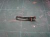
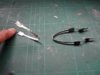
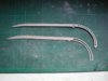
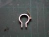
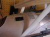
A good question and I wish I had an equally good answer, but I don’t! At the moment the fairings aren’t attached at all.


My idea is that the first few flights will be without them whilst I “fine tune” the bungees to get the correct amount of spring, which I’d want to do anyway, then once I’m happy with the undercarriage I’ll attach the fairings, possibly using silicon sealant if I can’t think of a way to make them easily detachable.


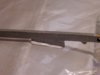
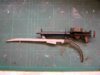
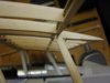
As I was answering Steve’s question I thought I might as well add this photo.


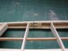
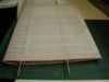
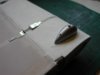
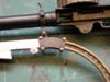
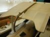
I’ve added a couple details to the decking, namely the transparent window and a (non-functional) inspection hatch; the side doesn’t look as empty now.


View attachment 262901
 

Attachments

  • decking 19.JPG
    decking 19.JPG
    2.3 KB · Views: 0
Thread owner
I’ve given up on the spruce for the interplane struts and decided to use strip pine wood from B&Q as I did for the undercarriage.


First the blanks are cut out and then bolted together for the final shaping of the profiles.


View attachment 262902


Once the profiles are correct, a couple of hours with the Dremmel and a sanding block and we have a set of reasonable struts.


View attachment 262903


The struts will not be attached rigidly to the wings but will be allowed to “swing” slightly in a spanwise direction. To enable this to happen the fixings are (at the moment) closed loop adaptors, which also allow for some adjustment in the effective length of the struts; they are screwed into hardwood blocks drilled and tapped to suit.


View attachment 262904


The struts themselves will be attached to the fixings by piano wire pins and the whole lot hidden by the interplane bracing wire attachment covers.


View attachment 262905


I’m having a few doubts about the strength of the closed loop adaptors for this critical job; they are made from brass and I’m wondering if I should really make my own fixings from 2mm threaded steel rod. I’ll certainly give it a go and if it’s not too difficult a job drilling a 1mm hole in 2mm threaded rod then steel fixings it will be!
 

Attachments

  • interplane 1.jpg
    interplane 1.jpg
    1.4 KB · Views: 0
  • interplane 2.jpg
    interplane 2.jpg
    2.1 KB · Views: 0
  • interplane 3.jpg
    interplane 3.jpg
    2.4 KB · Views: 0
  • interplane 4.jpg
    interplane 4.jpg
    2.5 KB · Views: 0
After some time away I just caught up with this thread.

Grahame this is beautiful. :respect1: :)
 
Thread owner
I have decided to stick with the closed loop adaptors for the inter plane strut attachment points; after all I used them to connect the cabane struts and Warren girders on the Elf and they’ve stood the test of time. Some of the steel 14Ba bolts have sheared off and been replaced but the closed loop adaptors are still fine.


The aileron control horns are made from 0.5mm galvanised steel with 2 pegs soldered in place to make them more secure in the aileron leading edge.


View attachment 262906


The aileron LE has balsa blocks to support the hinges and one is routed out to also accept the horn, the plate soldered to the hinge pins will add further strength.


View attachment 262907


As there are 4 control horns, all of which will be interconnected, it is important that they are all as near as possible identical; therefore once they had been “roughed out” I joined them together with a pin through the main actuating hole for the final filing to shape and a jig ensured that they were epoxied in the same relative positions on the ailerons.
 

Attachments

  • aileron control horn1.jpg
    aileron control horn1.jpg
    1.7 KB · Views: 0
  • aileron control horn2.jpg
    aileron control horn2.jpg
    2.4 KB · Views: 0
Thread owner
I’ve now covered the wings and I have to admit that the Solartex shows no inclination to “lift” from the under cambered section, the wood was pre-treated with Solarlac Clearcoat, which greatly increases the strength of the bond with the Solartex but I’m going to stick to my original idea and also stitch the fabric to the ribs just in case.


View attachment 262908


Covering is one of my favourite parts of modelling; it is at this stage that the model stops being a “construction” and starts to become a model aircraft. It always gives me a boost to see the “solid” shape of the model.


Then again the boost might just come from the use of copious amounts of Clearcoat in the confines of the shed!!!
 

Attachments

  • wing 18.jpg
    wing 18.jpg
    1.9 KB · Views: 0
Looking Good there Grahame,

Just make sure you tie something to your leg before starting with the ClearCoat !! :hehe:

Regards.......Mark
 
Thread owner
I’ve not managed a lot of modelling this last week; at the weekend it was the Teesside Model Flying Clubs’ annual 2 day model air show and a lot of my time’s been taken up helping to get that organised. It was a fabulous weekend and once again we were blessed with excellent weather.


I’ve got 2 of the wings stitched and taped; the stitching went just as I thought it would, no problems but mind numbingly boring! If you’ve every built a scale model and thought that adding stitching and rib tapes just isn’t worth the effort this photo with the evening sun casting shadows might change your mind.


View attachment 262909


When actually working on the wing the stitching and tapes don’t seem to stand out very much at all, but when in the air and the light catches them they are really noticeable even at a considerable distance so they definitely are worth the effort. Admittedly I’d use simulated stitches if the wing didn’t have such a pronounced under camber.
 

Attachments

  • wing 19.jpg
    wing 19.jpg
    2.6 KB · Views: 0
\ said:
If you’ve every built a scale model and thought that adding stitching and rib tapes just isn’t worth the effort this photo with the evening sun casting shadows might change your mind.
I think every part of this build shows just how worth it it is to take the extra effort. Watching this build progress has really increased my understanding and appreciation of the aircraft.

She's going to be a real beaut in flight too!
 
Just catching up with your excellent progress made to the S.E.5A Grahame,it certainly has come on leaps and bounds since I have been offline,well done the model is a real credit to your model building skills.
 
Thread owner
Good to have you back online Barry,


The wing covering has come to an abrupt halt as I’ve run out of natural Solartex, I didn’t think that it would take more than the 2 rolls but I’ve still got one complete wing to cover and also the top surface of another.


While I wait for the Solartex to arrive I’ve made a start on the Lewis gun. The stock will be made from layers of ply, as the shapes are quite complex I’ve used 2 laminations of 1/32nd ply for each layer to make the cutting easier but it’s still quite a delicate job. The trigger is from thin brass sheet.


View attachment 262910


With the various pieces glued together and a simple barrel from rolled paper and various bits of tubing it’s starting to take on the semblance of a Lewis.


View attachment 262911


I’m still searching for something to form the basis of the magazine
 

Attachments

  • lewis 2.jpg
    lewis 2.jpg
    1.8 KB · Views: 0
  • lewis 1.jpg
    lewis 1.jpg
    2.3 KB · Views: 0
Grahame mentions the soldering of joints on his model at various stages of the construction,some people do not realise the destructive long term nature of caustic fluxes,if left un-attended they can easily weaken critical fittings.

A quick and efficent fix for ensuring that there are no traces of flux, is to brush baking powder into the joint,scrub with a stiff artists brush and dry off,paint the joint soon as possible.

Never under estimate the amount of damage surplus flux can cause.
 
Thread owner
I finally found the basis for the magazine, a ring cut from some 32mm waste pipe with a 1/64th ply top. I wasn’t sure how to make the “ribs” but taking inspiration from the excellent models produced by Johnny and GW, to name but 2, I decided to cut the “spokes” from card and it’s worked really well. I’m now on with a second magazine to fit in the holder attached to the instrument panel.


View attachment 262912


It’s amazing what a few bits of bent tin, half a dozen pins and a coat of paint can do; while there’s no way that this could be described as a “super-scale” Lewis gun it certainly looks the part, a bit of “dirtying up” and the illusion will be complete
 

Attachments

  • lewis 3.jpg
    lewis 3.jpg
    2.2 KB · Views: 0
The Lewis gun looks great - looks great painted up, makes for a very authentic looking metal finish.

I really like your approach to modelling too and the use of everyday materials to solve tricky problems.
 
SE5a - Se5A?

I started building in about 1937 (very young!) but not long after the war I discovered girls, motorbikes etc so did not get back to the hobby (I think of it as a hobby, not a sport) until about 5 years ago. I like building, I really love experimenting, but as a New Boy on your block I was fascinated to find Grahame's write-up on the Se5A - I decided a month ago to make my first attempt at a biplane, specifically this one. I have bought the Simmance plans, 71" model, and I shall follow Grahame's efforts with great interest. I am also looking forward to the Shuttleworth restoration being completed.

I shall have little or nothing to contribute to this "club" but I shall follow it with great interest. Thanks guys.
 
Thread owner
Linney


Welcome to the forum; if there’s anything with your SE5a that you think I might be able to help you with you only have to ask and why not start an “under construction” thread while you’re about it, it’s always interesting to see how other people do things. I could send you the jpegs for the instruments, which would certainly save you a lot of time and effort; if you want them just send me a PM with your email address.


Grahame


It’s been a monotonous few days but the last two wing panels are now stitched and the rib tapes applied, a lot of work with not a lot to show for it.


The emergency tank is from litho plate and shows the results of not following the old adage “ measure twice, cut once”!! The double row of rivets was originally embossed in the wrong place; when I put the litho plate in position it just didn’t look right and a quick check of the measurement showed where I’d gone wrong. Luckily annealed litho plate is to some extent “reworkable” and as the tank will be covered with Solartex a touch of filler completed the repair / alteration.


View attachment 262913


To work out the positions and sizes of the various bits I used several different photos as well as 3 view drawings; all the measurements required a different conversion factor to get to the actual measurement I needed for the model and I got one of them mixed up.


The retaining straps, which will be added after the tank is covered, are made from “bean tin” material, or to be more accurate corned beef tin material, joined by 14BA bolts, I didn’t think litho plate would be strong enough for this job because the ends are not fastened to the tank but left “floating”.


View attachment 262914
 

Attachments

  • tank 1).jpg
    tank 1).jpg
    1.8 KB · Views: 0
  • tank 2.jpg
    tank 2.jpg
    2 KB · Views: 0
\ said:
I started building in about 1937 (very young!) but not long after the war I discovered girls, motorbikes etc so did not get back to the hobby (I think of it as a hobby, not a sport) until about 5 years ago. I like building, I really love experimenting, but as a New Boy on your block I was fascinated to find Grahame's write-up on the Se5A - I decided a month ago to make my first attempt at a biplane, specifically this one. I have bought the Simmance plans, 71" model, and I shall follow Grahame's efforts with great interest. I am also looking forward to the Shuttleworth restoration being completed.I shall have little or nothing to contribute to this "club" but I shall follow it with great interest. Thanks guys.
Linney, don't put yourself down, everyone has something to offer and sometimes the fresh new approach of a beginner sometimes can take the old hands by surprise!!

Welcome to the forum, we look forward to following your experiences.
 
Thread owner
Before I covered the tank with Solartex I added the flanges for the 2 sumps; it may seem a bit strange to do this but in modelling it is quite often better to do things “in the wrong order” and this is one such case. The sump and flange will look like a single unit in the end but doing things this way the covering was much easier to do and it’s made for an apparent neater edge around the sumps.


The rivets are a lot less obvious now the tank has been covered and the frayed tapes added; the reason the tank is from litho plate and not paper as I used for the Elf is because ironing the Solartex in place would have flattened the embossed rivets.


View attachment 262915


The sumps themselves were made using the plunge moulding method. They could just as easily been carved from balsa but I like to try out new techniques and although I’ve known of this way to produce plastic mouldings “for ever” I’ve never actually done it before. It really is simple and if you want to see how CLICK HERE. (link not working I'll try to sort it out later)
 

Attachments

  • tank 6.JPG
    tank 6.JPG
    1.9 KB · Views: 0
Thread owner
The next job on the centre section is the Foster mount made from laminations of 1/64th ply. The inner section is 3 laminations with the 2 outer sections having 2 laminations each making 7 laminations in total, which involved some delicate work with the scalpel!


View attachment 262916


The Lewis gun mount is made from “bean tin” side plates joined by 14BA bolts with brass tube spacers; whilst it will run up and down the track as per the full sized I think it will eventually be glued in position otherwise I’ll have to make a working locking mechanism!


View attachment 262917


A general view of the Foster mount in position on the centre section.


View attachment 262918
 

Attachments

  • foster 1.JPG
    foster 1.JPG
    2 KB · Views: 0
  • foster 2.jpg
    foster 2.jpg
    1.5 KB · Views: 0
  • foster 3.jpg
    foster 3.jpg
    2.5 KB · Views: 0
Looks great! That mount for the lewis gun is such a distinctive feature of the se5a. The view from the cockpit is really starting to look the part now - all it needs is a little silk scarf and a pair of flying goggles!
 
Thread owner
To ensure that the Foster mount is a good fit on the centre section I first covered the gluing area with cling film, applied a generous amount of 5 min. epoxy / micro balloons to the mount itself and then pressed it firmly in place. The mixture soon becomes like putty and can be moulded to a rough shape, then before it’s had time to fully harden it can be trimmed with a scalpel; it is then left to fully cure.


View attachment 262919


The Lewis gun mounting is a substantial casting so I’ve used aluminium sheet for the main hoop,


View attachment 262920


Painted matt black, given the graphite treatment and bolted to the Foster mount carriage it really looks like a substantial piece of metal.


View attachment 262921


Although not obvious from the photos the front section of the Foster mount has had paper sides added with rivets embossed, these will show up better when it’s painted PC10 and weathered. The gun carriage track is painted using Humbrol brass and brass / matt black


View attachment 262922
 

Attachments

  • foster 4.jpg
    foster 4.jpg
    1.7 KB · Views: 0
  • lewis 4.jpg
    lewis 4.jpg
    1.6 KB · Views: 0
  • lewis 5.jpg
    lewis 5.jpg
    2.8 KB · Views: 0
  • lewis 6.jpg
    lewis 6.jpg
    2.1 KB · Views: 0
Status
Not open for further replies.
Back
Top