
You are using an out of date browser. It may not display this or other websites correctly.
You should upgrade or use an alternative browser.
You should upgrade or use an alternative browser.
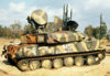
Steves shilka
- Thread starter Steve Brodie
- Start date
- Status
- Not open for further replies.
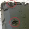
The ambiguous fitting location(s) of the two rear tow points
View attachment 275085
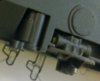
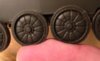
Fitted the other two shock absorbers onto the chassis;
View attachment 275087
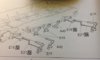
drilled out a couple of holes to attach the front strakes and cracked on with the suspension arms, now these are interesting, sad I know but; the instructions show them been added and I assume glued into their locating slots, as their isn’t any ‘do not glue’ logos, so they have been glued in.
View attachment 275086
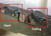
A couple of trailing arms for two suspension arms are built (not glued ) and added to the suspension side, but why ?, if the full arms don’t move why leave the trailing arms free to move ? and there is no play in the suspension, I was expecting them to ‘hang free’ if the model was lifted in the air but they don’t.
View attachment 275088
Yet the box art states they are movable, all very strange.
View attachment 275089
Onwards we go, other side next.
View attachment 275085
Fitted the other two shock absorbers onto the chassis;
View attachment 275087
drilled out a couple of holes to attach the front strakes and cracked on with the suspension arms, now these are interesting, sad I know but; the instructions show them been added and I assume glued into their locating slots, as their isn’t any ‘do not glue’ logos, so they have been glued in.
View attachment 275086
A couple of trailing arms for two suspension arms are built (not glued ) and added to the suspension side, but why ?, if the full arms don’t move why leave the trailing arms free to move ? and there is no play in the suspension, I was expecting them to ‘hang free’ if the model was lifted in the air but they don’t.
View attachment 275088
Yet the box art states they are movable, all very strange.
View attachment 275089
Onwards we go, other side next.
Attachments
G
Guest
Guest
Keep the good work coming Steve! Those workable tracks are very nice.
On the subject of kit instructions, I really do wonder if the manufacturers actually ask real model makers if they make sense. It seems to me that this is an area where great kits are let down.
On the subject of kit instructions, I really do wonder if the manufacturers actually ask real model makers if they make sense. It seems to me that this is an area where great kits are let down.
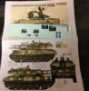
spookily, these arrived today;
View attachment 275132 View attachment 275133
I only emailed BNAthis morning as the decals hadnt arrived, ordered back end of November, but as they explained a lot of orders were only just reaching their destinations due to the Christmas mail.
View attachment 275132 View attachment 275133
I only emailed BNAthis morning as the decals hadnt arrived, ordered back end of November, but as they explained a lot of orders were only just reaching their destinations due to the Christmas mail.
Attachments
G
Guest
Guest
Good attention to detail there Steve.
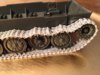
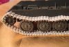
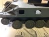
Wow, those tracks fit like a charm, had to add a few more links, but great sag and detail;
View attachment 275229 View attachment 275230 View attachment 275228
Front disc fell off 2nd road wheel, lol.
Also, take it back about the suspension, now that the glue has set for 48hrs it works quiet well;
View attachment 275231
View attachment 275229 View attachment 275230 View attachment 275228
Front disc fell off 2nd road wheel, lol.
Also, take it back about the suspension, now that the glue has set for 48hrs it works quiet well;
View attachment 275231
Attachments
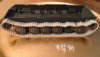
View attachment 275244 View attachment 275245 View attachment 275246 View attachment 275247
Looks like the sag will have to go, doesn't look like the tracks even touch the top of the road wheels, very taught system.
Looks like the sag will have to go, doesn't look like the tracks even touch the top of the road wheels, very taught system.
Attachments

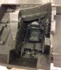
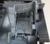
Ever had that sick, sinking feeling when you realise you have glued something on wrong !!  , Well I had that feeling last night, whilst I was constructing the drivers area, more on that in a bit, I was test fitting the ‘tub’ to the chassis but for the life of me couldn’t work out why it wouldn’t sit true, plus two locating holes seemed to be missing, it was then I had the sinking feeling as I looked at the hull plate and realised I had glued it on upside down, 3 days ago
  !!!. I assumed, obviously incorrectly, that the ribbing was part of the hull, where in fact it was for the underside. PANIC !!, a fresh blade in the knife and some very careful scoring and 10 minutes later I had managed to remove the plate without any damage and glue it back on the right way round.
")
The drivers compartment builds into a nice representation of the innards, 4 main pieces and a couple of small add-ons go into its construction, along with a couple of pieces for the side wall. Pedals, hand brake are all separate parts along with a ‘joystick’ steering lever. The seat has a nice texture to it and the whole unit is constructed from 5 pieces and fits into a slot in the floor, does seem a long way back though.
View attachment 275410 View attachment 275409
, Well I had that feeling last night, whilst I was constructing the drivers area, more on that in a bit, I was test fitting the ‘tub’ to the chassis but for the life of me couldn’t work out why it wouldn’t sit true, plus two locating holes seemed to be missing, it was then I had the sinking feeling as I looked at the hull plate and realised I had glued it on upside down, 3 days ago !!!. I assumed, obviously incorrectly, that the ribbing was part of the hull, where in fact it was for the underside. PANIC !!, a fresh blade in the knife and some very careful scoring and 10 minutes later I had managed to remove the plate without any damage and glue it back on the right way round.The drivers compartment builds into a nice representation of the innards, 4 main pieces and a couple of small add-ons go into its construction, along with a couple of pieces for the side wall. Pedals, hand brake are all separate parts along with a ‘joystick’ steering lever. The seat has a nice texture to it and the whole unit is constructed from 5 pieces and fits into a slot in the floor, does seem a long way back though.
View attachment 275410 View attachment 275409
Attachments
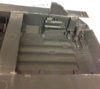
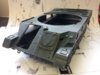
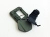
Got the drivers multi access hatch built, want to get the inside painted along with the interior, then i can tape the whole lot shut for when i paint the exterior;
View attachment 275948 View attachment 275949 View attachment 275950
Also built up the upper hull, have to align the side panels with the top plate and then the lower hull. Fitted okay, but some nasty attachment sprue points to clean up (on the side angles!!);
View attachment 275951 View attachment 275952
Attachments
Thanks, bit slow at the mo, with this and the ZSU-57-2 build, plus trying to finish off the Tamiya 1/48 JGSDF Type 10 - needs a few touch ups so hopefully out with the airbrush on saturday and get it finished andthe Shilka internals.great work Steve getting there bit by bit hope mine will turn out like yours do
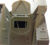
found a great reference image, for the inside of the Shilka's driving compartment, steel grey seems to be the instrument surround colour not black as per Meng ")
View attachment 276091
View attachment 276091
Attachments

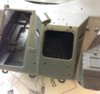
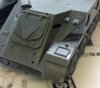
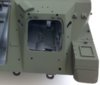
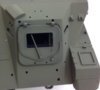
Go the airbrush out and NATO black base coat followed by Matt white for the interior;
View attachment 276259
Outside around nd the hatch and the hatch painted (field grey)
View attachment 276260 View attachment 276261 View attachment 276262
View attachment 276259
Outside around nd the hatch and the hatch painted (field grey)
View attachment 276260 View attachment 276261 View attachment 276262
Attachments
- Status
- Not open for further replies.
Legal Notice
scalemodelling.co.uk is a privately operated online discussion forum. All content posted by members reflects their own views and opinions and does not necessarily represent those of the forum owners or administrators. While reasonable efforts are made to moderate content, no responsibility is accepted for user-generated material. By using this site, you agree to comply with UK law and the forum rules.