Theme editor

Scale Model Shop

Wardell Bridge

Status
Not open for further replies.

Peter

New member
Joined
Mar 20, 2017
Messages
96
Reaction score
0
Points
0
1/3
Thread owner
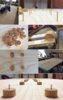
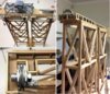
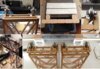
I started this project in October 2016, and now I am halfway through. So the following initial posts will be what has been done already, up to this date. Please do not expect any great detail, in fact it is quite rudimentary due to lack of modelling experience. However, I am having lots of fun working it out, and the challenge of building it.

This project started when the local maritime museum received the original control console (1963) for the Wardell (NSW, Australia) lift-span bridge. I was asked if the console could be used to operate a model bridge. However, they had no bridge or anybody to build one. I thought it would be better if I build the bridge anyway, because the motors and electronics for it will largely depend on the size of the bridge. Soon afterwards I found out that they wanted a boat to traverse under the bridge as well.

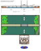
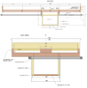
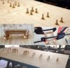
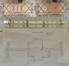
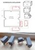
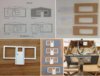
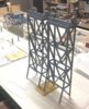
I wanted to build a small model, but the museum insisted that I use a dedicated space (2400 x 1200 mm) for the display - not including the console. Problems started from the start, nobody could give me a copy of the electrical schematics or the plans for the bridge. So I had to reverse engineer the console, and use photographs to draw scale (1/72) plans for the bridge. The later started from two tape-measured dimensions; the length of the span, and the width of the road.

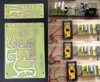
The console needed interpretation. The current bridge operator has never seen this console before, but was able to tell me what each control component did. I soon found out that it was not a simple matter of raising and lowering the lift-span. There is a lengthy and purposeful sequence to its operation. But not only that, the museum is hoping I can make it child-proof as well. That is, the bridge is not allowed to work out of sequence, like dropping the bridge span on the passing boat.
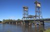
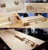
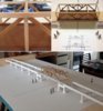
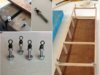
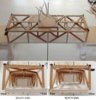
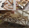
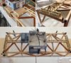
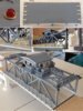
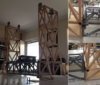
The actual bridge.
View attachment 278443
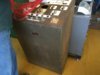
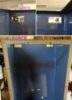
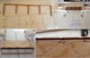
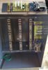
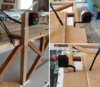
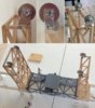
The console.
View attachment 278444
 

Attachments

  • control panel.jpg
    control panel.jpg
    2.4 KB · Views: 0
  • 0_Wardell Lift-Span Bridge.jpg
    0_Wardell Lift-Span Bridge.jpg
    2.1 KB · Views: 0
Thread owner
From October to December, 2016, I was figuring out how to make this project become a reality. My knowledge of electronics is old school, so I tend to design things in the same way. The console components are older still, and the main switches were custom made for the bridge. My first task was to make a map of the control panel, and a schematic of the switches. But first I had to gain access to the console.

The basic sequence in operation is:
  1. Boat is waiting for bridge to rise. The vessel traffic light will show red (stop).
  2. Road traffic lights are turned on and shows a flashing amber light. Also a bell is heard.
  3. The bridge controller, in the span hut, looks through an inverted periscope to make sure nobody, or a vehicle, is on the span.
  4. When all clear, the road traffic lights go to red.
  5. The four gates are closed. The gates along the footpath also has a partition to close across the footpath.
  6. The bridge then needs to be unlocked. In the hut there is a lever switch similar to a hand lever for switch train track points.
  7. The bridge is raised all the way to the top.
  8. When it reaches the top, the vessel traffic lights for the vessel (up/down stream) turns green. Opposite vessels see a red light.
  9. After the vessel passes, the bridge can be lowered. It is lowered about 60%, then inched down, bit by bit, until resting on the ground.
  10. The bridge is locked again.
  11. Gates are opened and the road traffic lights switch from red to green.

The control panel.
View attachment 278445

Internal wiring, and stripping away unnecessary wires.
View attachment 278446
 

Attachments

  • 2_Bridge Model update_ Stripping Wiring Harness.jpg
    2_Bridge Model update_ Stripping Wiring Harness.jpg
    2.9 KB · Views: 0
  • 1_Bridge_Control panel basics.jpg
    1_Bridge_Control panel basics.jpg
    2.6 KB · Views: 0
Thread owner
The museum workshop did not have enough room for the display table, so I am building it in my lounge room.
The console part, due to its weight, is modified at the museum.
The display table is 2.4 m x 1.2 m. It is resting on two trestle horses.

View attachment 278464

Wood is cut, screwed, and wood puttied the recesses.
The slit you see going across the tabletop is for guiding the boat under the bridge.
 

Attachments

  • 3_Bridge Model update_display table.jpg
    3_Bridge Model update_display table.jpg
    3.2 KB · Views: 0
Thread owner
The display table will be resting on a prefabricated steel frame. The control box, which houses the motors for the bridge and boat, needed to fit through this frame. I had to keep this in mind while designing the box and motor pulley systems.

View attachment 278465
Here is a rough drawing on how the pulley systems will work.
View attachment 278467

construction for the control box. It has two access doors. If any repairs are needed one is required to go under the table, open the doors, to access the pulley csystems and electronics. The box (now) is a separate item from the display table. It will be attached to the table when both items are complete and sent to the museum for assembly, electrically and pulley cables.
View attachment 278468
 

Attachments

  • 4_Bridge Model update_working compartment (Box).jpg
    4_Bridge Model update_working compartment (Box).jpg
    3.7 KB · Views: 0
  • Motor cabling.png
    Motor cabling.png
    7.1 KB · Views: 0
  • Bridge display plan.png
    Bridge display plan.png
    5.7 KB · Views: 0
Thread owner
Electronically, my first project was to build a DC power supply unit (PSU). This will enable me to experiment and test other circuits for the project.
The PSU is to fit inside the console, next to those three large terminal brackets. The museum president and curator liked to look of it and suggested to see if I can make it a part of the display. So now the console box will also be a sort of a (wire) diorama as well.

To do this, I decided to paint the inside of the box somewhat dark so as to highlight the wiring. The front console panel will be replaced by a clear perspex sheet. At the bottom, about 200 mm, a portion of the steel front panel will cover the perspex and act as a kick-plate. This is to protect the perspex from accidental breakage. The console diorama will have a hidden border of LED strips to light it up.

The console exterior will still have its antiquated look about it. It has been rust inhibited and satin lacquered.

The photos showing the multimeter indicates the three DC voltages needed for the display. 24 volts for console lamps and LEDs, 12 volts for motors and relays, and 5 volts for logic circuits and servos.

View attachment 278469
 

Attachments

  • 5_Bridge Model update_DC Power Supply circuit.jpg
    5_Bridge Model update_DC Power Supply circuit.jpg
    3.7 KB · Views: 0
Thread owner
It was time to start making the bridge. The first part is to anchor the bridge footings. I had no access to a lathe, or funds to justify 2400 mm length of 32 mm doweling ($60), since I was only going to us about 500 mm. So I cut up a piece of board off-cut and filed the footings to size.

I used bamboo skewers, as doweling, to anchor the footings.
View attachment 278472

Wood putty was used the eliminate the line between the footing and the tabletop.
Then came the bridge piers and girders.
View attachment 278474

You will notice that the bridge slopes away at each end.
View attachment 278473
 

Attachments

  • 6_Bridge Model update _footings.jpg
    6_Bridge Model update _footings.jpg
    2.5 KB · Views: 0
  • 8_Bridge Model update _girders.jpg
    8_Bridge Model update _girders.jpg
    3.8 KB · Views: 0
  • 7_Bridge Model update _piers.jpg
    7_Bridge Model update _piers.jpg
    3.8 KB · Views: 0
Thread owner
Gave the bridge an (acrylic) undercoat. The white area on tabletop is where the river is. Three coats, and sanding, has been applied so far to the river. I am not sure what to use for water. There is a lot of area, and cost, for using silicon. At the moment I am leaning towards using a high gloss enamel, a teal sort of colour. If the water was the main focus, I could justify the cost, but the focus is in operating the bridge.

Those white knobby bits inside the girders are cable clips for wiring to the bridge span.
The holes along the lateral side of the bridge is for contact terminals between the bridge and lift-span. The reason, is that the span has vessel traffic lights installed. So the span hut will hold some electronics and a rechargeable 9 volt battery. The battery gets recharged while the span rests on the bridge. This will eliminate a loose wiring harness between bridge and span.
View attachment 278475

Outside the bridge are a number of Fender Piers (FP), aka Dolphins. The outside sets of FP have navigational lights (red and green LEDs)
View attachment 278476
The remaining piers (dowels) will be installed when the river surface has been decided upon. You can see the outer pier has a hole through it - for installing the nav light.
 

Attachments

  • 10_Bridge Model update _Fender piles.jpg
    10_Bridge Model update _Fender piles.jpg
    2.4 KB · Views: 0
  • 9_Bridge Model update _under-structure undercoat.jpg
    9_Bridge Model update _under-structure undercoat.jpg
    2.5 KB · Views: 0
Thread owner
I need a break from the tabletop, and start focusing on some other parts which need to be resolved. I looked everywhere for narrow pulley heels, but non were suited. So I decided to make my own. I used washers and solder. I knew that if I could sweat the solder between the washer surfaces, nothing (short of heat) will pull them apart. So I experimented and found the right combination of solder amount and heat to do the job. It turned out quite well.

View attachment 278477
 

Attachments

  • 11_Making the pulley wheels.jpg
    11_Making the pulley wheels.jpg
    3.2 KB · Views: 0
Thread owner
I spent a few days scrapping rejected electronic equipment to scavenge for parts. It was fun to pull something apart for a change. From an old analog TV set I found some good 8 watt speakers. However, on their own there was no way to mount them without the diaphragm becoming restricted. So I had to make a bracket housing for them. I used 3 mm MDF board, and some vinyl mesh. These speakers will be mounted into the console.

View attachment 278478

Holes were cut out, of the rear part of the console, to accommodate the speaker brackets, wiring harnesses between console and control box, and mains power socket.
View attachment 278479

View attachment 278480
 

Attachments

  • 14_Bridge Model update_Speaker slots.jpg
    14_Bridge Model update_Speaker slots.jpg
    2.4 KB · Views: 0
  • 12-Bridge Model update_Console connectors.jpg
    12-Bridge Model update_Console connectors.jpg
    1.1 KB · Views: 0
  • 13_Bridge Model update_Speaker encasement.jpg
    13_Bridge Model update_Speaker encasement.jpg
    3.5 KB · Views: 0
Thread owner
Back to the bridge. I decided to construct the lift-span portion first. It has unsolved issues with it, and working on it gives me that time and focus I need to see what needs to be done. This is my first modelling job, and it has been a huge learning curve for me. The main thing, for me, was not to get too caught up in detail. I know this may sound horrible to some, but I decided to keep it simple and used 6 mm square wooden slats for steel girders. Both the curator and me did not want to spend too much time and money on reproducing the finer bits.

Before starting on the framework, I needed to wire the electronics to the span base first. In this way, there will be no strain on the frame while cutting trenches into the wood. The electronics involved here include the spring contacts, and navigational lights. I used wire cabling obtained from scrapping TVs etc. The wires were routed to the far side of the span where the framework pillars will be. They will later be routed up into the span hut.

View attachment 278483

I saw on the Internet how a railway modeler used a template for framework. So I did the same.
View attachment 278484

Inlaid the wiring.
View attachment 278485

Used wood putty to fill the trenches.
View attachment 278486
 

Attachments

  • 20_Bridge Model update _Span part 6.jpg
    20_Bridge Model update _Span part 6.jpg
    2.9 KB · Views: 0
  • 19_Bridge Model update _Span part 5.jpg
    19_Bridge Model update _Span part 5.jpg
    2.9 KB · Views: 0
  • 16_Bridge Model update _Span part 2.jpg
    16_Bridge Model update _Span part 2.jpg
    2.2 KB · Views: 0
  • 15_Bridge Model update _Span part 1.jpg
    15_Bridge Model update _Span part 1.jpg
    2.7 KB · Views: 0
Thread owner
The span needed four cable anchoring points. I thought that they may also need to swivel so as to release any cable twisting over time. I decided to use fishing swivels soldered onto bolt heads. I filed the heads flat to assist in increasing a stronger bond. The span itself should weigh no more than one kilogram. The soldering joint should easily handle 250 grams each. The right side photo shows where these will be installed.

View attachment 278487

Partially completed framework.
View attachment 278488

Not long after these photos, I went around the framework and inserted 2.5 mm dowels (skewers) through many of the joints. Some joints actually have two skewers, one adjacent to the other. At first I thought this would be pointless drilling through a dowel, but I discovered that is not necessarily so.
View attachment 278490
 

Attachments

  • doweling two.png
    doweling two.png
    3 KB · Views: 0
  • 18_Bridge Model update _Span part 4.jpg
    18_Bridge Model update _Span part 4.jpg
    3.4 KB · Views: 0
  • 17_Bridge Model update _Span part 3.jpg
    17_Bridge Model update _Span part 3.jpg
    2.7 KB · Views: 0
Thread owner
Now that the console box will also be a diorama I thought it would not hurt to include extra lighting. That is, the DC voltage outputs already have a fuse, so I decided to add a blown fuse indicator to them. Normally the green LED will be on, indicating that particular voltage line is on and okay. However, if the fuse blows, the power gets diverted through the red LED instead. Hence the indication.

The spare vacant set is also incorporated into the power supply circuit board. I was not sure if a 12 volt 2 amp supply would be enough to handle both the motors and relays at the same time. But if there will be an overload, I can easily add another 12 volt regulator to compensate.

View attachment 278491

Here you can see the blown fuse indicator circuit added to the power supply unit.
Below, it is attached to the console interior.
The terminal brackets have been cleaned up and new number labels attached (01-60).
View attachment 278492
 

Attachments

  • 38_BMU_DC Power Supply circuit installed.jpg
    38_BMU_DC Power Supply circuit installed.jpg
    2.7 KB · Views: 0
  • 21_Bridge Model update_DC Blown fuse indicators.jpg
    21_Bridge Model update_DC Blown fuse indicators.jpg
    3.3 KB · Views: 0
Thread owner
Back to the lift span. I finally finished the framework. The top portion now has to accommodate a hut, balconies for auxiliary equipment, and gangways.
Below is a top view of the span. The plan for the base plate and gangways; cut and filed from 3 mm MDF board.

View attachment 278493

The slots along the edges are for attaching matches as railing posts. The bottom right photo also show the floor of the hut. Its edges will serve as a gluing anchor for the walls.
View attachment 278494

I had to install the cable anchoring points to know how far to make the gangway. Those rollers are modified micro-switch actuator levers. These are utilized as bumper rollers to eliminate any chances of the span getting caught, or hooked up, to the bridge towers. The black U-shape device is an optocoupler. This device is a light switch which gets triggered once a blind is inserted into the U-gap. The blind will be attached near the top of the bridge tower. Once triggered, the vessel (boat) traffic lights, on the span, will switch over from red to green.
View attachment 278497

Now that the optocoupler has been attached, its wires, along with the others, can also be routed to the hut. The wires were fed under the top framework so they could be fed up through the hut floor.
View attachment 278498

By this time I worked out how to install the lateral bumper rollers. I used a pencil sharpener to cone the wooden square ends. Pulled rollers off the micro-switch actuators, and used a nail and super glue to install them. The bumper roller above the optocoupler had to be filed for clearance. It looks fairly cramped-up in the corners.
View attachment 278499

I need a break for awhile from uploading. There is still some more to upload before reaching to my present progress.
I hope this will follow what is expected of a diorama, though you have not yet seen much of it so far.
 

Attachments

  • 26_Bridge Model update_Span Bumper Rollers.jpg
    26_Bridge Model update_Span Bumper Rollers.jpg
    2.7 KB · Views: 0
  • 25_Bridge Model update_Span Wiring to Hut.jpg
    25_Bridge Model update_Span Wiring to Hut.jpg
    3.3 KB · Views: 0
  • 24_Bridge Model update_Span lift attachments.jpg
    24_Bridge Model update_Span lift attachments.jpg
    3.9 KB · Views: 0
  • 23_Bridge Model update_Span hut layout_2.jpg
    23_Bridge Model update_Span hut layout_2.jpg
    2.2 KB · Views: 0
  • 22_Bridge Model update_Span hut layout_1.jpg
    22_Bridge Model update_Span hut layout_1.jpg
    2.6 KB · Views: 0
What a brilliant project I wish you well in your endeavour and can't wait to see the finished article actually working

Regards

Colin
 
First of all welcome to the forum Peter, and what a ambitious and interesting project to start with.
 
Thread owner
Thank you Colin and Ian for your encouraging words.

Just got back from having dinner with friends. I'll try now to catch up with the down loads.

Here are the vessel traffic lights, one set at either side of span. I used the same type of LED assemblies used for the blown fuse indicators in post #13. These wires have also been routed to enter through the hut floor.

View attachment 278506

The external equipment for operating the span is stored on the balcony areas. I used wooden blocks to simulate the boxed areas seen on the real bridge.
View attachment 278507

Here is the hut plan and using 3 mm MDF board for the walls and roof. I used 2 mm perspex for the windows. The window frame and doors is from Bainbridge board. The doors are just drawn on.
View attachment 278508

The gangway railings are made from matchsticks and bamboo skewers. The wire screen is nylon fly-screen.
View attachment 278510

Here is the painted span. The laptop computer shows what the real hut looks like.
View attachment 278511

The span woodwork is now finished and painted. The road and footpath railings have also been included. The base structure is also painted. I found some small narrow washers that fit perfectly over the navigational LEDs. They now look like light bezels/beacons. The road section will get painted when I paint the rest of the bridge road.
View attachment 278512
 

Attachments

  • 28_Bridge Model update_Span Boxed Containers.jpg
    28_Bridge Model update_Span Boxed Containers.jpg
    2.4 KB · Views: 0
  • 27_Bridge Model update_Vessel Traffic Lights.jpg
    27_Bridge Model update_Vessel Traffic Lights.jpg
    3.7 KB · Views: 0
  • 29_Bridge Model update_Span Hut-1.jpg
    29_Bridge Model update_Span Hut-1.jpg
    2.8 KB · Views: 0
  • 30_BMU_Span Gangways.jpg
    30_BMU_Span Gangways.jpg
    4 KB · Views: 0
  • 31_BMU_Span_ Gangways_Boxes.jpg
    31_BMU_Span_ Gangways_Boxes.jpg
    3.8 KB · Views: 0
  • 32_BMU_Span_ Undercarriage and Railings.jpg
    32_BMU_Span_ Undercarriage and Railings.jpg
    3.1 KB · Views: 0
Thread owner
The bridge towers were next. The 30 cm rule gives an indication of its size. The longer leg portions is the side, with the footpath, which goes into the bridge girders. The shorter ones only penetrate the road base which overhangs the girder. I used many dowels for this part of the towers.

View attachment 278513

Here is how I installed the dowels. They are a snug fit and requires a block of wood to push them in. I used PVC glue.
View attachment 278514

It doesn't look it, but I used just over 11 m of square wooden slats (Tasmanian Oak) for the towers.
View attachment 278515
 

Attachments

  • 35_BMU_Bridge Piers-3.jpg
    35_BMU_Bridge Piers-3.jpg
    2.8 KB · Views: 0
  • 34_BMU_Bridge Piers-2-dowling.jpg
    34_BMU_Bridge Piers-2-dowling.jpg
    3.1 KB · Views: 0
  • 33_BMU_Bridge Piers-1.jpg
    33_BMU_Bridge Piers-1.jpg
    2.1 KB · Views: 0
Thread owner
Now was the time to make the pulley wheel brackets for the top of the towers. I used aluminium plate.

View attachment 278516

After both sides were cut and filed, it was time to assemble them. The axle bolts were trimmed . The pulley wheels were already made, as shown in post #9.
View attachment 278517

Here, they have been mounted onto the towers.
View attachment 278518

These photos only has the towers resting in place to show how it would look assembled.
View attachment 278519
 

Attachments

  • 40_BMU_Bridge Piers-4.jpg
    40_BMU_Bridge Piers-4.jpg
    3.3 KB · Views: 0
  • 39_BMU_Bridge Pulley Brackets-3.jpg
    39_BMU_Bridge Pulley Brackets-3.jpg
    3.2 KB · Views: 0
  • 37_BMU_Bridge Pulley Brackets-2.jpg
    37_BMU_Bridge Pulley Brackets-2.jpg
    3.1 KB · Views: 0
  • 36_BMU_Bridge Pulley Brackets-1.jpg
    36_BMU_Bridge Pulley Brackets-1.jpg
    3.5 KB · Views: 0
Thread owner
Now a gangway was needed on top of the towers.
View attachment 278520

View attachment 278521

Completed and painted. The only part not painted are the pulley wheels. Actually, I had a bit of trouble securing two of the wheels without them binding onto the washers. The clamping down of the brackets would twist the bracket onto the axle. Some filing of the bracket holes, for better alignment, alleviated the problem.
View attachment 278522
 

Attachments

  • 43_BMU_Bridge Piers painted.jpg
    43_BMU_Bridge Piers painted.jpg
    3.6 KB · Views: 0
  • 42_BMU_Bridge Pier Gangway-2.jpg
    42_BMU_Bridge Pier Gangway-2.jpg
    4.1 KB · Views: 0
  • 41_BMU_Bridge Pier Gangway-1.jpg
    41_BMU_Bridge Pier Gangway-1.jpg
    3.4 KB · Views: 0
Status
Not open for further replies.
Back
Top