
Just received the Roden 1:144 Boeing RC-135V/W Rivet Joint (Kit No.349) and was prompted by Dave Ward to leave a review. Here goes...
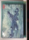
Box: Thin-gauge, top-opening 370mm x 240mm x 46mm with artist's depiction of aircraft.
View attachment 460963
No declaration of finished model size, but can be calculated from the details on Page 1
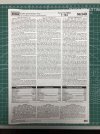
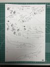
Instructions: Single A3 sheet flat-folded to form 4 pages.
View attachment 460965View attachment 460966View attachment 460967View attachment 460968
Page 1 gives background and specifications
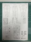
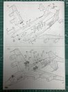
Page 2 is the sprue map & symbol list
Pages 3 & 4 are the assembly steps
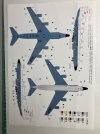
Painting & Decalling:
A separate A4 sheet gives this info...
View attachment 460969
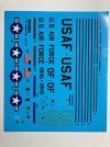
Decal Sheet:
View attachment 460970
The flags on this are incorrect.
There is also a break in Decal 11 (the LH red line) - this is as-printed since the carrier film is intact.
Caracal Models will be releasing a decal sheet (including RAF options) in September 2022 (Caracal Part No. CD144026)
Sprues:
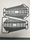
Frames A & B cover the wings:
View attachment 460971
The trailing edges of all 4 wingroots are deformed by 90 degrees from the normal. I thought this might be due to insufficient mould release agent as the first three points I inspected (two on Frame A and one on Frame B were on the same side as the ejector pin marks) but the fourth point is on the external side. I guess it is still technically feasible.
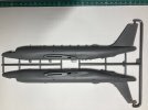
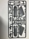
Frame C covers the 2 fuselage halves:
View attachment 460972
Note of caution here:
The port half has antennae moulded integrally - the forward one is thin and delicate and I have already caught it during basic handling
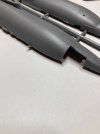
There is some flash to be dealt with, e.g.
View attachment 460973
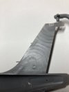
and are thin, so handling will need to be borne in mind. Also, the edges need a bit of TLC...
View attachment 460974
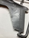
There is also evidence that the moulders have been tidying up as it came off the tool:
View attachment 460975View attachment 460976
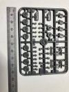
Frame D covers the main undercart, some antennae and the antennae heads:
View attachment 460977
There are 8x 11D on the sprue yet the instructions invoke 12x (Steps 2, 9 and 10).
Step 9 is incorrect - the 5x 11D along the top of the fuselage should be 5x 3D
There are also 2x 13D on this sprue that are not invoked anywhere in the instructions and, as yet, I cannot find a home for them.
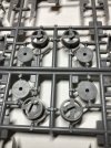
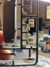
Frame E (there are two of these) cover the engines
View attachment 460978
Parts 7E (there are 4 in total) have a large (+) web in the middle - these will have to be cut out:
View attachment 460979
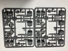
Frame F covers the remaining grey plastic parts and is home to a few errors:
View attachment 460980
Instructions Step 5 calls up parts 22F(16F) for the main undercarriage doors. This should read "22F(19F)"
Instructions Step 6 calls up parts 22F(16F) for the small undercarriage doors. This should read "15F(16F)"
Instructions Step 9 calls up parts 4F for the starboard horizontal stabiliser. This should read "1F"
Instructions Step 9 depicts the nose wheel undercarriage door but does not give a part number. This should read "7F"
Also worth noting, for those who want to build this aircraft with the wheels in the down position, the main undercart doors (19F & 22F) will both have to be bent at 90 degrees in 2 places (See Step 10)
View attachment 460981
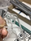
Frame G covers the clear parts
Two cockpit canopies are included but only 2G is called up (the one with the wider nose).
Clarity is not good...
View attachment 460982
I'm no expert as to whether this can be polished out, but I'll have a go.
I think this just about covers everything I have found or worked out. I'm not claiming that this is exhaustive but I do hope it will be of some use to others.
Box: Thin-gauge, top-opening 370mm x 240mm x 46mm with artist's depiction of aircraft.
View attachment 460963
No declaration of finished model size, but can be calculated from the details on Page 1
Instructions: Single A3 sheet flat-folded to form 4 pages.
View attachment 460965View attachment 460966View attachment 460967View attachment 460968
Page 1 gives background and specifications
Page 2 is the sprue map & symbol list
Pages 3 & 4 are the assembly steps
Painting & Decalling:
A separate A4 sheet gives this info...
View attachment 460969
Decal Sheet:
View attachment 460970
The flags on this are incorrect.
There is also a break in Decal 11 (the LH red line) - this is as-printed since the carrier film is intact.
Caracal Models will be releasing a decal sheet (including RAF options) in September 2022 (Caracal Part No. CD144026)
Sprues:
Frames A & B cover the wings:
View attachment 460971
The trailing edges of all 4 wingroots are deformed by 90 degrees from the normal. I thought this might be due to insufficient mould release agent as the first three points I inspected (two on Frame A and one on Frame B were on the same side as the ejector pin marks) but the fourth point is on the external side. I guess it is still technically feasible.
Frame C covers the 2 fuselage halves:
View attachment 460972
Note of caution here:
The port half has antennae moulded integrally - the forward one is thin and delicate and I have already caught it during basic handling
There is some flash to be dealt with, e.g.
View attachment 460973
and are thin, so handling will need to be borne in mind. Also, the edges need a bit of TLC...
View attachment 460974
There is also evidence that the moulders have been tidying up as it came off the tool:
View attachment 460975View attachment 460976
Frame D covers the main undercart, some antennae and the antennae heads:
View attachment 460977
There are 8x 11D on the sprue yet the instructions invoke 12x (Steps 2, 9 and 10).
Step 9 is incorrect - the 5x 11D along the top of the fuselage should be 5x 3D
There are also 2x 13D on this sprue that are not invoked anywhere in the instructions and, as yet, I cannot find a home for them.
Frame E (there are two of these) cover the engines
View attachment 460978
Parts 7E (there are 4 in total) have a large (+) web in the middle - these will have to be cut out:
View attachment 460979
Frame F covers the remaining grey plastic parts and is home to a few errors:
View attachment 460980
Instructions Step 5 calls up parts 22F(16F) for the main undercarriage doors. This should read "22F(19F)"
Instructions Step 6 calls up parts 22F(16F) for the small undercarriage doors. This should read "15F(16F)"
Instructions Step 9 calls up parts 4F for the starboard horizontal stabiliser. This should read "1F"
Instructions Step 9 depicts the nose wheel undercarriage door but does not give a part number. This should read "7F"
Also worth noting, for those who want to build this aircraft with the wheels in the down position, the main undercart doors (19F & 22F) will both have to be bent at 90 degrees in 2 places (See Step 10)
View attachment 460981
Frame G covers the clear parts
Two cockpit canopies are included but only 2G is called up (the one with the wider nose).
Clarity is not good...
View attachment 460982
I'm no expert as to whether this can be polished out, but I'll have a go.
I think this just about covers everything I have found or worked out. I'm not claiming that this is exhaustive but I do hope it will be of some use to others.
Attachments
-
 Box Art.JPG5 KB · Views: 35
 -
 Frame G.JPG5.3 KB · Views: 32
 -
 Instructions P1.JPG4.7 KB · Views: 29
 -
 Instructions P2.JPG4.3 KB · Views: 34
 -
 Instructions P3.JPG4.4 KB · Views: 26
 -
 Instructions P4.JPG4.4 KB · Views: 32
 -
 Painting & Decalling.JPG4.8 KB · Views: 38
 -
 Decal Sheet.JPG5.6 KB · Views: 30
 -
 Frame A_B.JPG4.6 KB · Views: 27
 -
 Frame C.JPG3.9 KB · Views: 30
 -
 Vulnerable antenna plus flash.JPG3.2 KB · Views: 28
 -
 Thin Tail.JPG4.3 KB · Views: 33
 -
 Tail Inner 1.JPG3.8 KB · Views: 31
 -
 Tail Inner 2.JPG2.8 KB · Views: 36
 -
 Frame D.JPG5.7 KB · Views: 29
 -
 Frame E_E.JPG5.9 KB · Views: 33
 -
 Removable Webbing.JPG6.5 KB · Views: 32
 -
 Frame F.JPG5.2 KB · Views: 33
 -
 Main Undercart Doors.JPG5.3 KB · Views: 34


