Theme editor

Scale Model Shop

SE5a CONSTRUCTION BEGINNING TO . . .

Status
Not open for further replies.
Thread owner
I totally agree with the comments from David and Barry. I’ve used closed loop systems to good effect in the past; they are reliable and light bit do require careful installation and I think this may account for some of the difficulties I had. I originally intended it to be a “dummy” pulley / cable system and as such I wasn’t as fastidious with the initial installation of control horns, pulleys, etc. as a would have been for a “working” system and we all know that “you can’t make a silk purse out of a sow’s ear”; used as it was intended it works fine.

I look forward to seeing the J1 develop, if you think I may be able to help with the instrument panel, or anything else, don’t hesitate to ask.
 
Thread owner
The attachment points for the tail plane bracing wires are not bolted on from the outside but attached internally and they are substantial items that exit the structure at acute angles, which would make covering after fitting quite awkward. To get around this problem I incorporated brass tubes into the TE and spar, after covering I passed a brass rod through the tube, soldered the attachment lugs to it and then bent it to the required angle; at this point the attachments were actually free to rotate. To check the angles were correct, and alter the ones that weren’t, before finally fixing them with a drop of cyano I rigged the tail plane using cotton.


View attachment 262697


Well it’s that time of year again when it’s considered antisocial to spend half the day down the shed building; people to visit, people visiting etc. so I’ll have to content myself with some “quick build” items.


Although C1096, upon which I’ve based the build so far, doesn’t have a headrest my model will as I think it is a quintessential part of the SE5a so this has been my first “quick build”. First a frame from 1/16th balsa and 1/32nd balsa skin.


View attachment 262698


Then cover with litho plate.


View attachment 262699


Finally glue in position.


View attachment 262700


Once the glue’s set I’ll add the frayed tapes over the joints; she’s looking more like an SE5a every day.
 

Attachments

  • tail 8.JPG
    tail 8.JPG
    1.7 KB · Views: 0
  • headrest 1.JPG
    headrest 1.JPG
    2.2 KB · Views: 0
  • headrest 2.JPG
    headrest 2.JPG
    1.4 KB · Views: 0
  • headrest 3.JPG
    headrest 3.JPG
    1.9 KB · Views: 0
I think that Grahame's approach is sound for another good reason. Having part of a model built gives motivation to do the next part. Without this,

a project can stay in the planning stage for ever.
 
Thread owner
“Quick build” project 2 is the Vickers machine gun; about ½ the barrel protrudes from the gun cover and only the rear and right hand side of the stock is visible but I’ve decided to build a complete unit. The extra weight will be negligible and in the event of an untimely end to the SE5a it may be salvageable as a useful item.


The barrel cover is 1/64th ply, soaked with ammonia and bent around 1/32nd ply formers that are temporarily mounted on piano wire to keep things aligned.


View attachment 262701


The outer skin is litho plate embossed using an old ballpoint pen with the louvers cut and eased out using a scalpel.


View attachment 262702


The barrel is aluminium tube and the flash suppressor plastic. The whole lot is painted matt black.


View attachment 262703


The trick now is to take a soft pencil, I used a 9b but anything from 4b upwards is OK, and scrape the “lead” to make some graphite dust, apply this and then carefully burnish with a lint free rag. The resulting finish is a perfect “gunmetal”.


View attachment 262704
 

Attachments

  • Vickers 2.JPG
    Vickers 2.JPG
    1.7 KB · Views: 0
  • Vickers 1.JPG
    Vickers 1.JPG
    1.6 KB · Views: 0
  • vickers 3.JPG
    vickers 3.JPG
    2.2 KB · Views: 0
  • Vickers 4.JPG
    Vickers 4.JPG
    2 KB · Views: 0
A tricky item to make convincing,but you have achieved a remarkable result using that favourite standby Litho plate.

If you need graphite dust then locksmiths sell bottles,I have just lubricated the rear car door with it,it has the advantage that it is not messy or gummy and will not freeze up,great for burnishing or weathering on scale models.

For smaller Vickers guns check out those ladies hair curlers for modification ! we need to look everywhere in scale modelling.
 
Thread owner
Continuing with the Vickers; here are the basic parts for the stock; the sides are 1/64th ply and the core ¼” balsa.


View attachment 262705


The “eject side” has an 1/8th lite ply spring cover. You can see the rivets, which were embossed from the reverse side using an old ballpoint pen as for litho plate


View attachment 262706


The ammo feed shoot is aliminium


View attachment 262707


It now needs 3 coats of sanding sealer and painting before adding the various levers.
 

Attachments

  • vickers 5.JPG
    vickers 5.JPG
    1.9 KB · Views: 0
  • vickers 6.JPG
    vickers 6.JPG
    1.7 KB · Views: 0
  • vickers 7.JPG
    vickers 7.JPG
    1.8 KB · Views: 0
Thread owner
The top covers are from litho plate but the levers need more strength so are cut from a “bean tin”.


View attachment 262708


The “eject side” having had the matt black and graphite treatment, which really brings out the rivet detail. The extension at the rear is the connection from the interrupt system and will have a copper pipe attached


View attachment 262709


The levers are pivoted using cut down pins and a 14BA nut and bolt, the handle is stained spruce.


View attachment 262710


The Vickers has proved to be the ideal “quick build” for this Festive Season consisting as it does of several small parts; I have been able to disappear down the shed for relatively short periods thereby keeping the peace but still managing to do some meaningful modelling.
 

Attachments

  • vickers 8.JPG
    vickers 8.JPG
    1.7 KB · Views: 0
  • vickers 10.JPG
    vickers 10.JPG
    1.7 KB · Views: 0
  • vickers 9.JPG
    vickers 9.JPG
    1.7 KB · Views: 0
Ah ! good old bean tinplate,we used to make those V-Wedge control line fuel tanks from this material,another good source of flat tinplate for free is those OXO tins.

Glad to see that you have integrated these small S.E.5A accessories into your building programme Grahame,albeit with breaks in the Christmas family environment
 
Thread owner
That takes be back a few years!! I well remember standing by the gas cooker waiting for the “magic moment” when the flame turns green. It is a real skill to be able to solder a leak free tank with a soldering iron that is constantly changing temperature.
 
You sure do enjoy using that litho plate! I'll have to look out for some, it looks like a great material to use. That vickers is really shaping up nicely, good use of graphite to give it a burnished steel look too.
 
Thread owner
Talking about tinplate tanks reminded me of an episode from my youth; I went to Apex Models in Leicester (was it in Church Gate?) and there was a ready-made tank and I remember thinking “Why would anyone spend that much money on something you can make yourself?” It was probably about 15p in today’s money but then again I only got 2/6d a week spending money!


To this day I still prefer to make rather than buy but the motivation is different. Take for example the Vickers that I’ve been working on over Christmas; I could have easily afforded to buy a plastic kit, which may well have produced a more accurate replica albeit probably not at 18% scale, but I wouldn’t have got half the sense of satisfaction that I got building from scratch.


Here are a couple of photos of the finished article.


View attachment 262715


View attachment 262718


An added bonus is the fact that it was built entirely from the “scrap box”, they don’t come much cheaper than that!


Alan


Just go your local printer and do a bit of grovelling, it works for me!


Grahame
 

Attachments

  • vickers 12.JPG
    vickers 12.JPG
    1.6 KB · Views: 0
  • vickers 11.JPG
    vickers 11.JPG
    1.7 KB · Views: 0
What kind of ammunition feed will this Vickers have? Was it by means of a belt or did it have a circular magazine ontop a bit like a lewis gun or something?

I was googling for images but only came up with the land based variants of the gun with belt feed.

Found a super 3D computer model of a Nieuport though which is very nice though - which I thought you might enjoy!

More images are on the CG Society forums here:

http://forums.cgsociety.org/printthread.php?t=55663&page=5&pp=15

n17finbf0.jpg
 
Thread owner
There were many variations of Vickers, mainly with the barrel cover and trigger / lock mechanism. Some had 1 or 2 sets of louvers some had none; some had flutes some had none and some of the ground based ones were water-cooled. The firing mechanism had to be altered for the plane-based models to enable it to be cocked and later for the interrupt system, but as far as I’m aware they all used belt feed.

In the case of the SE5a there is an aluminium magazine just in front of the instrument panel and the ejected cartridges exit via a hole in the gun cover. Just how I’ll model the belt with all those cartridges I’ve no idea.

One thing I’ve discovered whilst researching this project is that there appears to be no such thing as a “standard SE5a”; possibly straight from the factory but once in the field many were modified by the ground crew and there was a lot of “cannibalism” to keep the aircraft serviceable, a later version could easily have an older undercarriage fitted or even a complete wing!
 
It's quite an education watching this thread, really gets an idea of how the SE5A was put together.

I'm sure you'll find a terrific way of modeling that ammo belt!

A lot of the Vickers Guns have a sort of brass fairing for guiding the ammunition into the gun, is that something that'll feature on your model?
 
Thread owner
Because the Vickers takes up most of the space under the gun cover a built up structure is impractical and the cover itself can only be thin so I decided to use my least favourite modelling technique; a fibreglass moulding.


For a “one off” I won’t bother making a female mould so first a slightly undersized balsa plug is made, using the piece of decking I removed as a base, filled and sanded smooth.


View attachment 262719


The plug is then covered with cling film; a useful thing about cling film is that it is in fact to some degree heat shrinkable so it’s relatively easy to get it to conform to the double curves. Then the first layer of glass cloth and resin is added, the only glass cloth I have is very lightweight “wing skinning” woven mat, so several layers will be needed to build up the strength.


View attachment 262720


Whilst waiting for the resin to cure I remembered that a few years ago my brother give me an off cut of coarse carbon fibre matting, quite loose woven so ideal for forming around double curves, just one layer of this should be sufficient. But finding it was no easy task; somehow it had managed to fall down the back of the shelf, fold itself in half and hide behind a cardboard box, if it had stayed where it was put I’d have seen it when I got the fibreglass cloth out and saved myself a lot of trouble!


The fibreglass was removed and replaced with carbon fibre.


View attachment 262721


Don’t ask me why I didn’t just leave the original fibreglass in place and put the carbon fibre over the top; I put it down to euphoria about not having to do all those extra layers and too much Christmas spirit (most probably in the reverse order!!).


After leaving to cure overnight the edges are trimmed, the front cut away and the slot for the cabane bracing wire cut. I’ve used carbon fibre tows to put 3 “ribs” on the inside to really stiffen the whole lot up.


View attachment 262722


Finally a shot of the Vickers in position showing just how little in actual fact is visible from the outside; the stock is partially visible viewed via the cockpit opening and the inspection hatch.


View attachment 262723
 

Attachments

  • gun cover 2.JPG
    gun cover 2.JPG
    1.7 KB · Views: 0
  • gun cover 3.JPG
    gun cover 3.JPG
    1.7 KB · Views: 0
  • gun cover 4.JPG
    gun cover 4.JPG
    1.8 KB · Views: 0
  • Vickers 13.JPG
    Vickers 13.JPG
    2.7 KB · Views: 0
  • gun cover 1.JPG
    gun cover 1.JPG
    1.6 KB · Views: 0
Stinky,smelly fibreglass who wants it ! but no in this case it suffices to form the desired little cowl.

If anyone hates this stuff as much as myself then try this-Make the former exactly as Grahame has done,use the cling film technique as well,then soak brown paper strips in water,remove and cross layer using PVA adhesive as the resin,bake in the oven for a few minutes and ease from the plug,result one pattern that has not harmed the atmosphere and not stunk the place out.

You can even use blue foam as the plug,use the brown paper and when dry scoop out the foam with a potato peeler,told you that I was domesticated ! just an idea as a practical alternative to glass fibre.
 
Thread owner
Barry

I see fibreglass isn’t your favourite either!

Actually I suspect that statement isn’t entirely true and, as with me it’s the resin not the fibreglass that is the problem. Having discovered Poly C, fibreglass skinning is OK, if time consuming, but it hasn’t got the strength of resin.

I’ve never tried PVA / brown paper, I’ve heard of it used for skinning but does it have the strength to self support without being too thick?

To add to my post above; the best method to produce these mouldings is to use multiple thin layers, this is true for everything from fibreglass to paint, but I dislike the process so much that I’ll put up with the extra filling and sanding with its associated extra weight and time.
 
I’ve just caught up with your last few posts. I’m certain that if I were making the headrest I wouldn’t have gone to the trouble of cutting lightening holes in a short piece of 1/16” balsa. I know it all adds up but it must be low on the effort/advantage continuum line.

In a similar vein the machine gun is very impressive but then to cover it all up! Unless the idea is to have the cover easily removed to reveal the gun like a rabbit from a hat.

Did the cover only have a single coat of resin and was this enough to fully fill the weave or will a bit of filler be needed?

By the way Apex Craft was in Church Gate, Leicester, ably run in the 1950/60s by Ron Pepper and his son Graham. It was an excellent shop and on a Saturday afternoon it could get so crowded at times that you had to queue outside just to get into the shop. How things have changed in these days of buying on-line, mail order, etc.

Keep up the good work Grahame the SE5 is coming along fine.
 
Yes it is that smelly resin,after all it is a by product of petroleum and other nasties,some people use ordinary Tufcote fuel proofer as a binder,it does work but just as obnoxious.

Yes brown paper in three layers is very tough,another trick is to put a layer of gardening fleece betweeen the brown paper layers,tough as old nails.

Try a small test piece Grahame,if you need extra support then just leave a skim of bluefoam and skip the cling film,I built the Lancaster engine nacelles from this method.

BarryI see fibreglass isn’t your favourite either!

Actually I suspect that statement isn’t entirely true and, as with me it’s the resin not the fibreglass that is the problem. Having discovered Poly C, fibreglass skinning is OK, if time consuming, but it hasn’t got the strength of resin.

I’ve never tried PVA / brown paper, I’ve heard of it used for skinning but does it have the strength to self support without being too thick?

To add to my post above; the best method to produce these mouldings is to use multiple thin layers, this is true for everything from fibreglass to paint, but I dislike the process so much that I’ll put up with the extra filling and sanding with its associated extra weight and time.
 
Thread owner
This is a marathon post because since my last one I’ve not been able to up load any photos to my gallery, up until now that is; I’ve been preparing the posts as usual over the last few days so in fact this is several added together and I have to say I’ve been rather busy of the festive season! I’ve not done any editing using the benefit of hindsight so some details have “developed” throughout this one post.


Ron Pepper, I’d completely forgotten that. Definitely a name from the “good old days”!


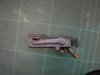
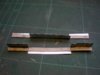
The weight saved by cutting holes in 1/16th balsa is minimal, although it does add up taken over a complete model, but as much as anything I like the aesthetics even if I’m the only one who sees it. I couldn’t use the weight argument with regards to the Vickers because it that case I actually added weight, albeit very little, but I though it worth it, even though not much will be visible on this model, because it is now a complete unit that may be able to be transferred to other models in the future. As for the effort in making the complete gun, it wasn’t an effort it was a pleasure!


One coat of resin was enough to give the required strength but being quite a loose weave meant that it needed a lot of filling but to me this was preferable to working with resin to add extra layers. I can’t say that I’ve really enjoyed this part of the build; from now on it will be OK but it started badly, I think as much as anything because I had the wrong attitude, I knew I wasn’t going to like it and that’s not the way to start things. There are a few more small mouldings needed for the SE5a and for these I’ll certainly try out the brown paper technique first and start with a positive attitude!


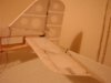
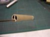
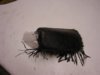
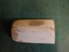
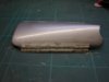
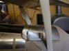
The inside of the cover.


View attachment 262724


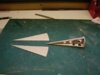
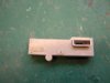
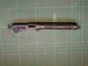
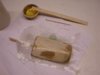
The resulting finish will be smooth enough to simulate metal so no need to cover it with litho plate, this is with just one coat of silver Solalac and not yet sanded.


View attachment 262725


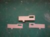
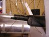
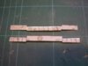
The next job is to make the 2 long “hinges” that attach the cover to the fuselage, they have loose pins, so the cover will be removable but not easily. Once again these are not working hinges, when the model has been painted etc and the cover fitted in place it shouldn’t have to be taken off again (unless I want to show off the Vickers!) so litho plate will suffice.


Here’s a series of photos showing the method of making a hinge.


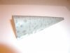
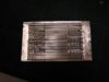
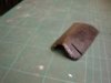
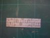
The litho plate “blank”


View attachment 262726
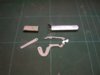

The first bends.


View attachment 262727


The second bends.


View attachment 262728


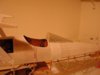
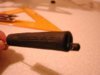
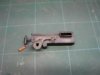
Bent around the hinge pin ready for trimming.


View attachment 262729


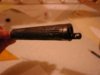
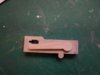
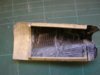
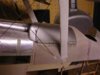
The assembled hinge glued to the cover.


View attachment 262730


When gluing hinges like this it’s obviously important to not glue the pin so use very little epoxy to “tack” the assembled hinge in place, take it apart and fill in any voids with more epoxy. The same applies when gluing to the fuselage.


View attachment 262731


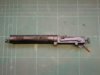
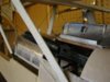
Some SE5a’s had an extra hatch towards the rear of the cover; I think I’ll add one to take away the plainness. With the bracing wire passing through the cover and the angle of the top “hinge” I didn’t think that it would actually work as such and would really just be used to hold the cover in place, but in fact it does allow the cover to be easily hinged open, I should have had more faith in the designer! Of course now I need to make a convincing mount for the Vickers, as I will be able to “show it off”.


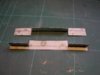
With the extra hatch and the other various fittings added the cover is looking a lot more business like.


View attachment 262732


With the cover hinged open the Vickers is visible in all its glory.


View attachment 262733
 

Attachments

  • gun cover 6.jpg
    gun cover 6.jpg
    2.2 KB · Views: 0
  • gun cover 5.jpg
    gun cover 5.jpg
    1.7 KB · Views: 0
  • gun cover 7.JPG
    gun cover 7.JPG
    1.6 KB · Views: 0
  • gun cover 8.JPG
    gun cover 8.JPG
    1.8 KB · Views: 0
  • gun cover 9.JPG
    gun cover 9.JPG
    1.7 KB · Views: 0
  • gun cover 10.JPG
    gun cover 10.JPG
    1.9 KB · Views: 0
  • gun cover 11.JPG
    gun cover 11.JPG
    1.6 KB · Views: 0
  • gun cover 12.JPG
    gun cover 12.JPG
    2.5 KB · Views: 0
  • gun cover 13.JPG
    gun cover 13.JPG
    2.6 KB · Views: 0
  • gun cover 14.JPG
    gun cover 14.JPG
    2.8 KB · Views: 0
Status
Not open for further replies.
Back
Top