Theme editor

Scale Model Shop

SE5a CONSTRUCTION BEGINNING TO . . .

Status
Not open for further replies.
Thread owner
This post will hopefully give you an insight into the thought and build processes that go into making each individual instrument. I decided to start with the air pressure regulator, which is positioned lower left on the instrument panel.


First of all I make a rough sketch showing the main components, which I will include, there’s no way that I could make a true miniature.


View attachment 262526


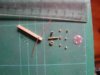
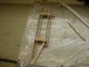
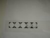
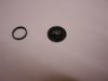
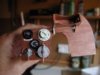
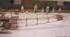
Then find suitable bits and pieces, in this case some copper wire and tube to fit, three 14BA nuts, a 2mm crimp, a 2mm nut and some 2mm threaded rod, litho plate and 1/8th square spruce.


View attachment 262527


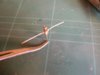
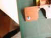
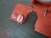
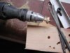
The wood has crossed holes drilled through and the wire soldered into position; the small tubes and 14BA nuts are then soldered on. The 2mm rod, nut and crimp are soldered together and the whole lot attached to the body using 5-minute epoxy.


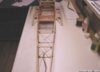
When the glue has set the body is cut down and finally sanded to length with the Dremell


View attachment 262528


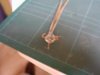
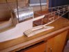
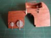
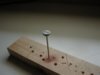
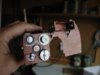
The wire is bent around suitable drill bits and the back plate glued on, again with 5-minute epoxy.


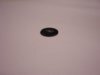
The appropriate bits are then painted with silver Solalac.


View attachment 262529


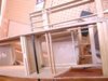
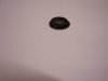
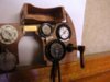
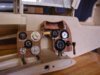
Sorry about the blurred photo, taking photos this close really needs a tripod!


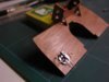
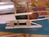
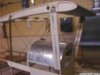
The finished regulator in position but not glued, I’ll leave that until all, or at least most, of the instruments are made.


View attachment 262530


The instrument panel has had a coat of stain as has all the wood that will be visible though the cockpit opening. Note the half round cut outs and the metal brackets.


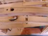
Another photo of the regulator in position.


View attachment 262531
 

Attachments

  • instrument 1.0.jpg
    instrument 1.0.jpg
    2.5 KB · Views: 0
  • instrument 1.1.jpg
    instrument 1.1.jpg
    2.2 KB · Views: 0
  • instrument 1.2.jpg
    instrument 1.2.jpg
    1.8 KB · Views: 0
  • instrument 1.3.jpg
    instrument 1.3.jpg
    2 KB · Views: 0
  • instrument 1.4.jpg
    instrument 1.4.jpg
    2.3 KB · Views: 0
  • instrument 1.5.jpg
    instrument 1.5.jpg
    2.3 KB · Views: 0
Absolutely beautiful Guy. A pure pleasure to watch this aircraft model develop and get an insight into your thought processes as you progress it.

There is actually a book out about the building of a model of HMS Warrior, I am sure there would be just as much a market for this thread to be developed into a book.
 
Grahame,you have entered the construction of these tiny instruments in the true spirit of modelling by making things from scrap,you need that feel for these things something which you obviously have,it is amazing just how much time you can expend on these small details which set scale modelling apart from any other form of model making,but by producing each individual item as a model in itself that interest is maintained,there is a definate thought pattern developing here,and we are experiencing that rare opportunity to be able to look over your shoulder into your workshop and see how it is done,I am certain that your ongoing tutorial will bring inspiration to many,and for that we are grateful.
 
I'm watching this thread with the greatest pleasure!!

You are doing some brilliant work here Greyhead!
 
My oh my, what a beauty! You mentioned earlier that you are concerned about the undercamber, and the covering possibly pulling away. I don't know what you plan on using for covering, but I recently covered my 57" Albatros C.III with Polyspan and Stix-it (heat activated) for adhesive. The covering was then sealed with nitrate dope and painted with butyrate. To date, the covering has stayed firmly attached with absolutely no signs that it may detach from the rib. It may be worth your consideration.

Once again, fantastic work, a real pleasure to watch this beauty unfold!
 
Thread owner
The lower wing stubs are built individually; at this stage the front spars are balsa. After leaving everything to thoroughly set they will be removed and the unit slid onto the spruce spars that go right through the fuselage.


View attachment 262532


Although not obvious from this photo the plans are drawn on tracing paper, this has a couple of advantages, firstly I’ve only had to draw one wing stub, for this one I’m actually working from the back of the plan and secondly it means that since I’m building both wing stubs from the same drawing they should be identical.


With the balsa spars removed the unit can be test fitted to the fuselage.


View attachment 262533


This shows the front spars and leading edge.


View attachment 262534


Still thinking about the covering / under camber, all suggestions gratefully received!
 

Attachments

  • wing stubs 1.jpg
    wing stubs 1.jpg
    2.2 KB · Views: 0
  • wing stubs 2.jpg
    wing stubs 2.jpg
    3 KB · Views: 0
  • wing stubs 3.jpg
    wing stubs 3.jpg
    2.9 KB · Views: 0
Thread owner
Waiting for the glue to set etc. whilst building the wing stubs gave me the opportunity to make the air pump selector; I chose this for no other reason than it connects to the regulator that I’ve already made, but before I go into the construction some general thoughts on instrument panels.


Having a good quality photo of the finished item is very useful and it might seem reasonable to scale the photo appropriately and stick that to the panel but I assure you it would look terrible. Take for example the regulator that I made earlier, it looks completely different from the front, side and top and there are an infinite number of variations between these extremes. A photo is 2 dimensional; our brains compensate to some degree when looking at a photo but put one into a “real” situation, such as a model’s cockpit and it looks just what it is flat! There are also shadows that move dependent upon the viewing angle; a very basic 3 dimensional representation will always look far more convincing than the most detailed photo.


The selector consists of 2 parts, the dial and the lever, so the first thing is to separate these, I do all the manipulation using Adobe Photoshop but I’m sure any photo editing software will do the job. There is an instant problem, some of the wording is missing, so failing more information I’ll make an educated guess and I think it is reasonable to assume that it is “FROM ENGINE & HAND PUMP”. Although I’m sure nobody will actually read the dial I feel that if at all possible the wording should be correct.


View attachment 262535


From the photo the dial is obviously aluminium, the illusion is created by the use of differing shades to simulate reflections, but once again these won’t work in real life. In the past I’ve used plain grey but it never looked very realistic, so this time I tried a different method and I’m really pleased with the results. I changed the grey to white, which of course doesn’t print out, reversed the image and printed it onto a transparency, when it was completely dry I painted the back with silver Solalac.


View attachment 262536


I had 3 failures before I managed to cut one good enough, this was then stuck onto 1/64th ply.


I had intended to use the lever as in “decoupage” pictures but it was too fiddlely to work with in paper so I made the lever from shim brass, a 2mm washer and a dress makers pin, all painted silver, the spindle is a 14BA bolt and a brass nut.


The backing is a simple disc of 1/8th balsa with some copper wire and brass tube .


The finished selector.


View attachment 262537


Another shot.


View attachment 262538


Notice the shadow has moved to the opposite side of the lever.


2 down, a lot more to go!!
 

Attachments

  • Instrument 2.1.jpg
    Instrument 2.1.jpg
    1.6 KB · Views: 0
  • instrument 2.2.jpg
    instrument 2.2.jpg
    1.2 KB · Views: 0
  • instrument 2.3.jpg
    instrument 2.3.jpg
    2.2 KB · Views: 0
  • instrument 2.4.jpg
    instrument 2.4.jpg
    2.3 KB · Views: 0
You could take a photo of yours and not tell it apart from the original.

That's when you know you have got it right!!

The attention to detail even stretches to an expansion loop in the copper tube, lovely!!
 
Thread owner
The recent spell of fine weather has produced a lull in the building schedule; not that I’m complaining, it’s nice to have a few good flying sessions this late in the season. Especially as this would have been my first week back at work after the summer break, being 60 has its advantages!


Whilst not being able to get on with any substantial building I’ve contented myself with a couple of instruments: radiator temperature and air pressure. The housings for these are identical, just the dials are different, so once one was done it was a case of “cut and paste”.


The unit consists of the dial and back plate printed as one unit on glossy photo paper and glued onto 1/64th ply, a plastic ring and a disc of acetate. It’s easier to finish the “rounding” of the back plate after everything is glued together.


View attachment 262539


Without the ring the unit looks like this.


View attachment 262540


With the ring added the unit looks so much more realistic! The photo doesn’t really show the difference to its full effect.


View attachment 262541


The instrument labels are simply cut out and glued in place, the wording is quite easy to read. Here’s a photo of the instrument panel so far, you can get a good idea of the size of the individual instruments from this shot


View attachment 262542


The panel fixers are made using a variation of the “glue drop rivet” system; in this case the glue is mixed with brass paint with a little matt black to tarnish it. With only one more instrument to make for this half of the panel it’s time to glue the instruments in place.
 

Attachments

  • instrument panel 4.jpg
    instrument panel 4.jpg
    2.5 KB · Views: 0
  • instrument 3.2.jpg
    instrument 3.2.jpg
    931 bytes · Views: 0
  • instrument 3.1.jpg
    instrument 3.1.jpg
    854 bytes · Views: 0
  • instrument 3.0.jpg
    instrument 3.0.jpg
    1.1 KB · Views: 0
Thread owner
Well the Indian summer continues, I’m glad to say, with the result that the instrument panel is far more advanced than I thought it would be. To finish off the left hand side all that’s required is the petrol selector.


The first job is to turn a knob; no lathe being available I used my Dremmel and a couple of needle files.


View attachment 262543


The knob is glued to a cocktail stick for easy handling during the preparation and to use as a spigot when gluing to the panel itself.


View attachment 262544


Once again the back plate is a simple printout glued to 1/64th ply.


View attachment 262545


The term instrument panel seems a bit of a misnomer; of the 5 “instruments” on this side of the panel only 2 are what I would call instruments but it has certainly made for an interesting build so far.


The small plastic rings added to the temperature and air pressure gauges came from my “useful items” box; these were originally from an electric toothbrush and are used to identify the different heads, I’ve been collecting them for years and just knew they’d come in one day! To try to explain what a difference these small additions make I’d used words like “convincing” and “realistic” but I think Barry’s description “come alive” really says it all.


Here’s another shot of the panel that shows how the acetate sheet in front of the dials brings the whole lot “alive”.


View attachment 262546
 

Attachments

  • instrument 4.0.jpg
    instrument 4.0.jpg
    2.6 KB · Views: 0
  • instrument 4.1.jpg
    instrument 4.1.jpg
    1.6 KB · Views: 0
  • instrument 4.2.jpg
    instrument 4.2.jpg
    2.6 KB · Views: 0
  • instrument panel 4.jpg
    instrument panel 4.jpg
    2.5 KB · Views: 0
Grahame,nice work with the improvised lathe,and why not ? for anyone who wants to have a go at making model instruments your techniques are inspirational,the office is a model in itself,nice photography as well,thank you.
 
absolutly amazing!! those dials do look sooo realistic. i could not get a picture of scale in my head but once you mentioned the plastic rings from the eletric toothrushes i knew exactly how big these dials where.

..and now i am even more impressed!

keep up the lovely work!
 
Beautifull Grahame, a work of art in itself and a model in its own right.

Your aircraft is going to become a collection of such masterpeices and will be stunning when finished.
 
Thread owner
The rear spars don’t go through the fuselage, they are just keyed into the ply ribs, the inner one has a doubler for the rear section. I had been a little concerned that this might weaken the wing stubs too much but with the 1/64th ply covering tying everything together they’re as solid as a rock


View attachment 262547


The slot is for the rear flying wires, which pass through the wing stubs into the fuselage. As these will have to be threaded through each time the model is rigged I will eventually build in some form of guide tubes but I’ll leave this until the model is test rigged before covering to ensure they’re in the correct position.


This underside photo shows the hole through which the wires enter the fuselage; it will have a piano wire “bearing” to prevent the wires cutting into the fuselage side.


View attachment 262548


The snake outer for the aileron control is securely attached with a few wraps of carbon fibre tows.


And finally a thank you to everyone for the positive feedback, it certainly encourages me to continue taking the photos and writing the posts. Not that I need all that much encouragement; I find it very useful to recap on the build, I quite often think of a better way to do things so it helps to generate new ideas for the next model.
 

Attachments

  • wing stubs 4.jpg
    wing stubs 4.jpg
    2.9 KB · Views: 0
  • wing stubs 5.jpg
    wing stubs 5.jpg
    2.4 KB · Views: 0
One of the things that I quickly learned with my Parnall Elf,was the fiddly assembly threading wire pins etc to fix the wings in place,biplanes to remain functional need plenty of planning right at the very early stages of construction,as shown here.

There are so many things to consider and the easiest solutions are usually the best ones as you have proven.

I am amazed how this model is coming along leaps and bounds !

As for the support,this is the very least that we can do to thank you for the continued detailed coverage of your lovely S.E.5A.
 
Thread owner
The cabane struts need cladding, for this I’ve used 3 layers of 1/16th balsa glued together “cross grain”.


View attachment 218893


They are attached to the struts with 5-minute epoxy, sanded to a streamlined shape, filled and then sanded again.


Before gluing to the struts I decided to add another pin just to be on the safe side!


View attachment 218894


The top decking from the tank cover to the rear of the cockpit and cladding of the rear cabane struts can’t be done until the instrument panel and all the controls etc. are fitted so it’s time to continue with the rear fuselage. As I mentioned before the rear fuselage is made from 1/8th square spruce and as such is very light but quite fragile, all the joints have had biscuits added which strengthens things up considerably but it was still very flexible.


Flexible is good if you hit something solid, things bend not break; but flexible isn’t so good if it allows the fin and tail plane to move relative to the wings! On the full size they used wire braces but button thread will suffice for a model.


View attachment 218895


Each section has a cross of thread; the very rear sections will be done after the fin and tail plane mounting is completed. The thread is locked with a drop of cyano at the corners and cross over points; and then given a coat of shrinking dope to finally tighten everything up.


View attachment 218896


The rear fuselage is now solid and hopefully any too heavy landing will break an easily replaceable thread and not a longeron!


Incidentally that is why the side coverings are laced, for easy removal / replacement during repairs and maintenance.
 

Attachments

  • cabane5.jpg
    cabane5.jpg
    1.4 KB · Views: 0
  • cabane6.jpg
    cabane6.jpg
    2.6 KB · Views: 0
  • fuselagerear8.jpg
    fuselagerear8.jpg
    1.9 KB · Views: 0
  • fuselagerear9.jpg
    fuselagerear9.jpg
    2 KB · Views: 0
And you will be surprised how much strength that internal rigging gives as well,the longerons on a full sized machine are quite frail until braced with swaged piano wire.

The pins on the strut cladding is a wise decision,how many times has the cladding migrated in flight on models ? they just seem to want to twist around.

Those struts really finish things off nicely.

At this rate Grahame you will have her flying by Christmas !
 
Thread owner
Barry

I first realised how much strength is imparted by button thread bracing when building the Elf wing; that was one thread were as this is a real “cat’s cradle”.

Cladding around metal always seems to move; well mine does anyway! The first pin was primarily to stop this but I decided that another pin through the joint for the top tube wouldn’t go amiss.

As for flying by Christmas, if you mean Christmas 2008 you might be about right!
 
Thread owner
The right hand side of the instrument panel wasn’t such a challenge.


The 3 dials are just “variations on a theme” and with 2 being bigger made things that much easier, the hand pump is a .22 cartridge with spruce handle and the flight plan holder is simply printed out twice and assembled decoupage style.


View attachment 262551


I quite like the “broken glass “ on the oil pressure gauge; a purely accidental scratch but I think very effective and true to life!


Metal panels have in the past caused me problems, but the method I devised for the air pump selector back plate has worked equally as well for the brass identification plate. That is reversing the image, printing it onto a transparency and painting the back with metallic paint; it certainly looks brass and not yellow


The complete panel. Just the compass needed before fitting to the model.


View attachment 262552
 

Attachments

  • instrument panel 5.jpg
    instrument panel 5.jpg
    2.6 KB · Views: 0
  • instrument panel 6.jpg
    instrument panel 6.jpg
    2.8 KB · Views: 0
Status
Not open for further replies.
Back
Top