Theme editor

Scale Model Shop

SE5a CONSTRUCTION BEGINNING TO . . .

Status
Not open for further replies.
Truly a great example of model making at it's best.

I really admire your creativity and inspired use of materials too. It all looks simple after you get to see how it's all done properly.

Like the miniature dremel lathe...great stuff! The way you look at each piece of the project as a tiny model in itself, the finished model is going to be a real joy. It really looks to be a labour of love.

The attention to detail shouts out from a mile away.
 
Thread owner
The first former is made from 2 layers of 1/16th balsa glued together “cross grained”, this is a good method when some extra strength is required but it doesn’t warrant ply of even lite ply; it has a 1/64th ply facing on the cockpit side. The other notched former is from 1/8th lite ply as this is also the front fin support. The centre former is also “cross grained” balsa as half the stringers actually end at this point.


View attachment 262553


Only 2 formers are fully notched because it is very easy to slightly miss align the slots, which results in wavy stringers, not a pretty sight!


The centreline stringer initially holds everything in place. I wanted to use spruce for the stringers but none was available and the model shop didn’t have any idea when they could get any so I’ve used basswood; I don’t think it’s as resilient as spruce but needs must!


View attachment 262554


The fin rear post is only fitted temporarily; the fuselage end plates have been made oversize to hold the fin post and will be finally shaped when all the stringers are in place.


View attachment 262557
 

Attachments

  • fuselage rear 10.jpg
    fuselage rear 10.jpg
    2.2 KB · Views: 0
  • fuselage rear 12.jpg
    fuselage rear 12.jpg
    2.8 KB · Views: 0
  • fuselage rear 11.jpg
    fuselage rear 11.jpg
    2.4 KB · Views: 0
Interesting that 'Balsaply' as it was called then,was in fact available from model shops back in the fifties-sixties,but production of this useful material ceased a long while ago,nothing to stop us from making our own stock,Scotch 3m spray adhesive is useful for this as it is very light.

Spruce is now a thing of the past and if you can find a supplier then cherish what he has in stock,its resiliance and springyness can never be surpassed,sometimes a word with the full size suppliers such as Slingsby Sailplanes,Kirbymoorside can bring in offcuts.

I like the early application of the sternpost to check to make sure that everything is in line,no easy task if something wants to twist out of shape.

Amazing simularity to a Tiger Moth in that last shot Grahame.
 
Thread owner
The centre stringer has had rear doublers and metal brackets fitted for attaching the fin; now to cut the extra slots and fit the rest of the stringers.


A length of cotton is stretched tight between the 2 formers already notched, the intervening formers marked and the slots cut using the Dremell with a cutting disc.


View attachment 262561


The stringers are added symmetrically; long right, long left, short right, short left and so on, this helps to avoid any unwanted twists in the fuselage.


View attachment 262562


The stringers stand proud of the formers apart from the first 2½, which will be ply covered, several of the stringers will eventually be removed from this area to save weight. But for now they add vital strength and it’s easier to get things even if all the stringers start from the same point.
 

Attachments

  • fuselage rear 14.jpg
    fuselage rear 14.jpg
    2.6 KB · Views: 0
  • fuselage rear 13.jpg
    fuselage rear 13.jpg
    2.8 KB · Views: 0
I like the stretched cord stringer locator Grahame,reminds me of the days we used to mark chalked lines onto the sides of aircraft to paint on the registrations,you outstretched your two hands between the two points with a knot in the centre,grabbed hold of the knot with your teeth,and twang ! as the chalk left the desired impression onto the surface.
 
Even a technique to ensure the stringers are perfectly true.

Is there anything you haven't thought about Grahame?
 
Thread owner
Over the last few weeks I’ve been doing a lot of thinking and considerable experimenting with rib stitching before committing to the actual model. Unfortunately the photos I took don’t really show anything of note; white thread on natural Solatex just doesn’t show up any differences!


View attachment 262564


The first question was “do I want to stitch the fabric?” – No I don’t; it will be a fiddly, time consuming job that will add weight but won’t add significantly to the scale appearance. In fact, as I later found out, at this scale and it must be said with my lack of expertise, the rib stitching looked less like the real thing than the simulated stitching.


So, “do I need to stitch the fabric?” – Yes I do; I know many people have no trouble with under cambered wings but I’ve had the covering pull away on a glider and with a model of this complexity it’s just not worth the risk!


I first tried Barry’s idea of three stitches with the rest simulated, this is where I found out that the simulated stitches looked better, I just couldn’t hide the knots. I rejected this method because with the stitches all being in the same position it would have ended up with three rows of different looking stitches running span wise along the wings, which would have looked very obvious.


Next I tried full stitching; as I had predicted very fiddly and time consuming and it didn’t look that good.


In the end I decided to just “wrap” the thread around the ribs without any knots, each stitch fixed with a drop of cyano. I find the easiest way is use a strip of paper with the stitch spacing marked on it placed along side the rib, make a hole in the appropriate position next to the rib using a pin, then use these holes to pass the needle and thread through.


View attachment 262563


The centre section is fabric covered on the underside and sheeted to the rear spar on the top; before the sheeting is fitted it shows how I’m doing the stitching.
 

Attachments

  • rib stitch 2.jpg
    rib stitch 2.jpg
    1.6 KB · Views: 0
  • rib stitch 1.jpg
    rib stitch 1.jpg
    2.2 KB · Views: 0
Grahame on reflection I think you have tackled this the right and most practical way,Dave Boddington used to say if you cannot reproduce a method in model form then at least simulate it in some way in order to look convincing,as artists of the art trompf school make things look as if you can touch them by simulating three dimensional effects,so model builders can achieve realism by cheating a little,the secret is to make the eye believe that what you are looking at is in fact real looking.

To this end I think that your model will look realistic at this scale.

Duncan Hutson was the one to do rib stitching on his many Tiger Moth models,not quite sure how he did it but it certainly looked realistic.
 
Thread owner
It’s strange how size affects things; I once built a Hawker Hind, the plan had offset bell cranks that imparted differential aileron to counteract adverse yaw. I modified the plan to incorporate the scale Frise ailerons, which were designed for this problem, only to find out latter that at this size they don’t work. Luckily I’d also used individual aileron servos so it was easy to “dial in” a bit of differential, which solved the problem.

I suppose it could be explained because the model has to fly in “full sized” air but it’s more difficult to explain why something replicated as the full size just doesn’t look right at a smaller scale, such as rib stitching!

The only slight problem I have with the rib stitching is the last stitch at the trailing edge, which has to go through the wood itself because the TE wouldn’t be strong enough at scale dimensions. It’s not really needed so it might end up as a “false” stitch if it proves too difficult / boring when doing all the wing ribs!
 
Grahame I once test flew a quarter scale Turbulent for someone,it had scale wing slots just as the full sized fixed ones,that flight was the most erratic test flight that I had done,in fact the model became almost uncontrollable and was glad to get her down on the ground.It seems that as you say sometimes things do not work in miniature,as they do normally on the full sized machine,normally as we know scale tailplane areas do not work on our models either and we need to increase the area,with slots and slats the effects can be quite alarming,the thing was this was the Precedent kit which should have ironed out the bugs,how many of these have been built and flown with these problems which were probably not understood by the builder ?

So whilst it is certainly wise to follow the designers build as regards construction ( after all they knew better than ourselves ) this does not always follow with some standard aerodynamic devices or concepts.

I once conducted practical tests with fixed leading edge slots and will elaborate on these some other time.
 
Thread owner
The centre section has had the top ply added and the covering finished. The rib stitching works well and was no problem to do. With the top frayed rib tape added it really looks the part, the under tape, which I’ve never used before, is quite visible and adds a lot to the finished effect.


View attachment 262565


Frayed tapes are nowhere near as complicated to make as serrated ones but there is a technique.


The Solatex is marked at the correct width, a small nick made with a sharp blade and the strips torn from the sheet; this ensures that the edges follow the material weave. Discard the first strip with only one torn edge; it will most probably be tapered anyway, then make another nick close to the edge and “tease out” a couple of threads, repeat for the other edge and you have a perfect frayed edged rib tape ready for ironing in place.
 

Attachments

  • rib stitch 3.jpg
    rib stitch 3.jpg
    1.1 KB · Views: 0
That looks better than I thought it would work out Grahame,good tip there on fraying the Solartex.
 
Thread owner
I was talking to a friend the other day about the instrument panel; he is also building an SE5a and has a photo which has the instruments in different positions from the one I have. I wonder if perhaps the plane “developed” as a result of reports from pilots about visibility of the instruments whist flying?


He liked the results of my build but said that in his opinion the thread didn’t explain the method fully enough. As I have just started the altimeter here’s a “blow by blow” description; I hope you don’t find it too boring!


I won’t go into the intricacies of Photoshop, but using mainly copy & paste, rotate and distort, the original photo is manipulated to produce an acceptable image with a resolution of 1200 pixels / inch. This is printed on photo paper and glued onto 1/64th ply; you now have to be very patient and wait for the glue and paper to be completely dry.


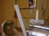
View attachment 262579


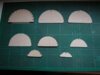
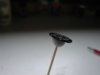
Cut out, not too close to the image and then sand away all the surrounding material. I use a sanding disc in my Dremel for this but it’s delicate work so be careful and turn the speed to its lowest setting, if you don’t have variable speed it might be advisable to do the last bit by hand. Whichever way you use be sure to always sand downwards away from the dial face, it’s all too easy to delaminate the photo paper.


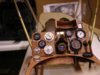
View attachment 262586


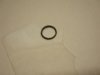
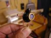
A cocktail stick and a piece of blue tack make a good holder whilst the edge is painted. Now you have to find or make a suitable ring; a search through the “useful items “ box will often yield a result, in this case the top from an air freshener refill, failing that start from scratch with a piece of Plasticard or similar material.


View attachment 262588


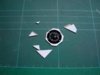
The ring is now painted and stuck to some acetate using “canopy glue”, which dries transparent, the excess trimmed away and the edge repainted.


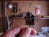
View attachment 262589


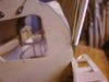
All that’s left to do now is to make the adjusting knob, from some plastic sprue, and assemble the parts.


The photo doesn’t show the finished instrument to its best, I just can’t photograph things this small and get the detail to show, but I assure you that once fitted into the cockpit it will look the part.


It seems to have taken longer to do this post than it did to actually make the instrument but I’m sure that’s not really the case!!!
 

Attachments

  • instrument 5.5.jpg
    instrument 5.5.jpg
    1 KB · Views: 0
  • instrument 5.4.jpg
    instrument 5.4.jpg
    1.6 KB · Views: 0
  • instrument 5.3.jpg
    instrument 5.3.jpg
    1.3 KB · Views: 0
  • instrument 5.1 ).jpg
    instrument 5.1 ).jpg
    1.7 KB · Views: 0
Thread owner
With the centre section removed for covering it’s the idea time to wrap the front cabane struts.


First of all the struts are given a coat of Solalac Clearcoat, which I’ve used for years to help the Solatex to stick.


View attachment 262590


I know the “industry standard” is Balsaloc, which I’ve also used, but in my opinion it’s nowhere near as good. With Clearcoat the Solatex won’t lift but if you do ever want to remove it, a run over the join with the iron and it can be peeled back without lifting the balsa fibres then rejoined as good as new. When the wing spars in my Albatos Dva broke I removed the entire wing covering from both wings, repaired the spars and then replaced the original covering; saved having to do all that paint work again!


It has another advantage in that the Clearcoat and the Solatex adhesive will bond without the use of the iron. It doesn’t “grab” immediately but if held in close contact it sticks after a few hours. This proved very useful for the base of the cabane struts where there is no chance of applying the iron.


View attachment 262591


I gave the struts a quick blast with the heat gun just to speed up the bond.
 

Attachments

  • cabane 8.jpg
    cabane 8.jpg
    2.5 KB · Views: 0
  • cabane 7.jpg
    cabane 7.jpg
    2.5 KB · Views: 0
Sorry Grahame,I had not realised that you were not aware of the fact that there are at least six different S.E.5A instrument panel layouts,by this I mean original ones and not the scores of replica machines built in recent years.

Just love this rundown on the instrument fabrication,as they say a photograph saves a thousand words,another excellent source of rims for the instruments are small rubber seals obtainable as boxes of assortments in those useful £ pound shops.
 
Thread owner
Barry

As my old mother used to say “you learn something new every day!”

The SE5a that I have detailed photos of the instrument panel for is a French restoration of C1096 “Maybe?”. This aircraft, at least the restoration, doesn’t have the headrest fairing, which I think really spoils it’s appearance. I’m certainly going to incorporate the headrest in the model so I will finish it as a different aircraft, unless I can find evidence that it did originally have the headrest. That means that I might well have at least a 5 in 6 chance of having the wrong instrument panel.

But I won’t tell anybody if you don’t!!!

Grahame
 
Grahame,

I am sure you will find the evidence you are looking for and if not it will only take a real enthusiast to spot a minor difference with your aircraft.

I am sure all these machines varied in fitments to the aircraft just as the Tanks,Ships, Vehicles and other Aircraft did between the various units operating the same types. I am sure that will give you scope for a little poetic licence without spoiling what is undoubtedly becoming a very fine looking model. From What I have seen so far who am I to argue...I am drooling over this one !!

I have always had a soft spot for the SE5-A ever since getting free scale plans for one years ago...meant for .10 - .15 Engines......I might just get around to doing one yet...but fitted with a PAW .19 as I have 2 of them sitting idle....Ok power to spare but I won't need full throttle on this one and the PAW exhaust will hide nicely inside that cowl plumbed up to the proper pipe too...!!

Regards......Mark
 
Thread owner
I’ve just spent 3 “modelling” days making the compass and I think it says a lot about scale modellers. Whilst many “sports” modellers voice their appreciation of my models it’s often suffixed with “but why bother?” Well all I can say is “if you feel the need to ask I can’t explain it to you” but I can fully understand their point, the model won’t fly any better and the details will only be visible if you peer into the innards of the model.


View attachment 262592


The pilots eye view of the instrument panel.


View attachment 262593


I now think the panel is finished but I’m sure I’ll find a few more things to do to it before it finally gets covered with the cockpit decking. Every time I look at the photos of the full size I notice some thing new but at the moment I don’t consider them worth the trouble adding but that always seems to change!
 

Attachments

  • instrument panel 7.jpg
    instrument panel 7.jpg
    3.1 KB · Views: 0
  • compass finished.jpg
    compass finished.jpg
    2.5 KB · Views: 0
Well words cannot explain the realism that you have achieved with that panel Grahame,this is what sets scale modellers apart,the love of producing something in miniature,that joy is something that says even if you cannot see it,or it does not assist the way that the model flies,it does not matter,you are achieving scale fidelity by fabricating these parts,the thing is also you have scratch built them from bits and pieces ! real model building and a real sense of achievment as well.

It makes me feel like hopping into that cockpit and flying her around the circuit.

The effort expended has been well worth it.
 
Thread owner
Barry


I think the answer is that we scale modellers’ build for our own satisfaction, or at least I do, which means that we strive for the current model to be better than the previous. If we want the model to fly then there are limits because the weight has to be controlled; my personal limit is if it can’t be seen from any angle that is the time to say, “why bother”.


I like to build as much as possible from scratch; it gives me a much greater sense of satisfaction and also saves money! An article in a magazine extolling the scale fidelity of a model jet had, amongst others, a photo of the undercarriage, which was truly amazing, but they were commercially available at a ridiculous price; not to my mind scale modelling more like scale assembling.


There are some things that up to now I’ve bought; wheels are one example, if these fail during take off or landing the result could well be to write off the model, but with the Williams Brothers problems I might have to bite the bullet and have a go this time.


Just to add substance to my last post about things developing after being “finished” here’s a photo of the compass now with its light!


View attachment 262594


I haven’t resolved my problem with the headrest; what I have found out is that it was development of the SE5a, the SE5 didn’t have one and neither did some of the early SE5as, whether or not C1096 was one of the early SE5as that didn’t have the headrest I don’t know, but I suspect it was.
 

Attachments

  • compass with light.jpg
    compass with light.jpg
    2.5 KB · Views: 0
Status
Not open for further replies.
Back
Top