Theme editor

Scale Model Shop

SE5a CONSTRUCTION BEGINNING TO . . .

Status
Not open for further replies.
It's great to see that cover after it's been filled, it's really coming together nicely.

I must admit I'm not a great Fan of Fiberglass either, it's such an unpleasant material to work.

Is the little projecting flap on the side the slot where the spent cartidge cases are ejected from?

Mental note **Must get some litho plate...**
 
Very businesslike Grahame,the strut bindings look very realistic as well,is that good old Solartex ?
 
Thread owner
Yes and yes: the spent cartridges are ejected through a hole in the cover and the deflector plate ensures that they don’t hit the rear cabane strut, presumably gravity makes sure they don’t hit the tail plane! The binding is solatex, a very versatile material.


Here’s a “quick build” that got lost in the confusion. It’s the oil reservoir for the interrupt gear; simply a plastic tube with a carved spruce handle and plasticard supports painted all over gloss black.


View attachment 262734


It is attached below the instrument panel and points forwards into the foot well. At the moment it’s full length but because of the way it fits it may interfere with the servos so I won’t actually glue it in place as yet. If necessary it will have to be shortened.
 

Attachments

  • Interrupt gear.JPG
    Interrupt gear.JPG
    1.7 KB · Views: 0
Thread owner
While the better half hit the sales I visited the model shop and bought the copper tube for the interrupt pipe and the snakes etc. for the elevator. I’ve now managed to “fix” the positions for the servos and therefore the interrupt reservoir; it didn’t need shortening.


Here’s a “pilot’s eye” view of the completed cockpit. Not much of the Vickers or the interrupt reservoir showing from this angle!


View attachment 262735
 

Attachments

  • cockpit 10.JPG
    cockpit 10.JPG
    3 KB · Views: 0
Well what can I say Grahame ? your S.E.5A cockpit looks so real,you have achieved wonders using simple basic materials,the secret is you made just the right choice and using your skills the results are excellent,you can be justly proud of the end product.

Another factor is that you have maintained a researched interest in your subject,another big factor that ensures success.
 
Thread owner
Barry

Thanks for the favourable comments; they’re much appreciated.

Grahame

And ditto to Richard and Alan for the posts below!

Grahame
 
Grahame, this is one of those models that is so beautifully put together that you could take a good quality photo of it and easily pass it off as the real item.

Absolutely superb and a joy to watch being put together.
 
What I enjoy about these build threads is seeing how the parts of the model come out of very straightforward materials. I especially enjoyed seeing how the various instruments in the cockpit were made and how authentic it looks assembled.

It's good to get the benefit of seeing the result of someone's experience, and glad you find the time to post so many work in progress images of your build as it progresses.
 
Thread owner
I’m always amazed at the number of models that seem to have had the radio gear added as an afterthought, decent models spoiled by a row of servos bang in the middle of the cockpit. I’m sure with a bit of forethought they could be mounted more unobtrusively and for the last few days I’ve been busy mounting the servos for the rudder and elevator; not the most “glamorous” of building jobs and as such it doesn’t make for a very exciting post, but nevertheless very important; for the moment the control cables are button thread.


What might be of interest is the linkage for the rudder / tailskid; the rudder servo arm has two 2mm bolts / nuts, the “quick links” are cut away to stop them fouling at maximum deflection.


View attachment 262736


The tailskid servo arm has it’s splined boss removed and is fitted on top of the rudder servo arm by the two bolts. The control cables are connected by piano wire links incorporating a “Z” bend to provide some shock resistance (thanks for the idea Richard).


View attachment 262737


This photo shows the double-decker arrangement more clearly.


View attachment 262738


Another thing that perhaps I should point out is that the front servo rail isn’t glued but fixed to the side rails by 2 servo screws. I find it quite awkward feeding servos between fixed rails, especially in the cramped interior of a model, so being able to slide one of the rails to widen the gap is very helpful.


When looking at one of my previous servo installations a fellow modeller pointed out that he wouldn’t be happy with 3 servos effectively held by just 2 screws. Well I’ve used this method for quite some time and had no problems; there’s no way the screws would sheer before the rail itself broke and routine maintenance ensures that the screws are always tight
 

Attachments

  • servo 3.JPG
    servo 3.JPG
    3 KB · Views: 0
  • servo 2.JPG
    servo 2.JPG
    3.2 KB · Views: 0
  • servo 1.JPG
    servo 1.JPG
    3.1 KB · Views: 0
Very neat Grahame and your thoughts on servo installation being an afterthought made me smile. I agree they should be an integral part of the original planning on any model and a part of your initial dry layout investigations.

There again I think I have changed the steam boat options about three times so far and I haven't fitted them yet!
 
Thread owner
How true Richard; my original drawings just ensure that the construction leaves enough physical space for the radio gear in a position where it won’t be too obvious, the exact positions of the individual items is continually updated as the build progresses but there comes a time when you have to make the final decision!
 
Thread owner
All the interior work is completed for the rear of the fuselage so the sides can now be covered; this involves a couple of things that I’ve never done before. The cockpit decking is fixed using dome headed screws that are then covered with the linen and the fuselage sides are laced, so I did some tests to try out my ideas first but no “in progress” photos because I didn’t know if the ideas would actually work!


View attachment 262739


My first idea for the screws had been to use a thin strip of litho plate embossed from the rear but I rejected this because the strip would show through the Solatex, pins would need holes drilling at least partially through the longerons so that was out. In a previous post I mentioned that I’d bought some very small beads, they’re called “Accent Beads”, from a haberdashery store and these have indeed proved to be the answer. I made a small indent using a blunted pin, filled it with slow cyano and placed a bead into it using a dampened toothpick to pick it up. From this photo you can judge just how small these beads really are.


View attachment 262740


Tomorrow I’ll start on the lacing.
 

Attachments

  • lacing 2.JPG
    lacing 2.JPG
    1.5 KB · Views: 0
  • Lacing 1.JPG
    Lacing 1.JPG
    2.1 KB · Views: 0
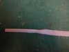
Very realistic Grahame,if I can at this point explain a bit about these devices and their real purpose-

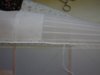
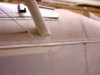
Take a look at many pictures of World War 1 aeroplanes,and you will quickly notice that maintenance in the field was far from perfect,in order to be able to inspect and more especially repair broken longerons etc the fabric was placed as a bag onto the fuselage,the sides and belly had flexible metal cleats made from what is best described as a malleable lead like material,if you want to inspect even today these applied in a relatively modern form take a look at a Tiger Moth belly,or a Rapide underside,you will see how beeswaxed twine is pulled between the cleats and the fabric pulled tight,at the end of the run it is simply looped around the cleat,then a fabric strip is applied over the twine and cleat combined,why beeswax ? well this easily takes and adheres to aircraft cellulose dope.

You can quite often see where an over zealous application of pulling the twine,has caused the fabric to buckle on WW1 machines,the correct way is to soften the doped area by applying a dope remover and then to stretch ! nine times out of ten not enough time in the field to do the job properly and that awful crinkled finish appears as is evident in photographs taken at the time.

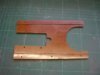
These days with metal monocoque construction only small round opening panels are needed to check the integrity of a structure,back then things were a bit more basic.

I hope this explains a bit more the purpose behind those little beads that you have used,that represent an important part of these wonderful old biplanes.
 
Thread owner
Barry


Thanks for the information; knowing what all these “scale bits and pieces” do in the real world is a true fillip and adds greatly to the enjoyment of building a scale model!


Grahame


The first job for the lacing is to make a hem on a strip of Solatex; here the fold line has been drawn with a soft pencil and a start made on folding, adhesive-to-adhesive.


View attachment 262741


When the folding is complete the hem is stuck together using the bare minimum of heat for the iron, we don’t want any shrinkage that would cause bending, then the non-hemmed edge "frayed". One strip is ironed in place first but of course the hem remains unstuck and can be lifted to make the stitching easier; this photo also shows the results of the beads once covered.


View attachment 262742


The next strip is ironed in place using the first as a guide, the stitching positions marked and pilot holes made with a pin. I found the easiest way to proceed was to stitch about 5 or 6 inches, leaving the stitches very loose, tighten 2 or 3 inches then continue stitching and tightening in sequence.


View attachment 262743


When the lacing was completed, as far as I can, the whole lot was given a coat of thinned dope to seal everything together. At the wing joints there is an aluminium cover, which is riveted to the front but held by the lacing for the rear section, so the lacing will have to wait until the wing stubs are covered. This will not be until after I’ve confirmed the positions of the wing bracing wires so will be some time yet!


View attachment 262744
 

Attachments

  • lacing 6.JPG
    lacing 6.JPG
    1.9 KB · Views: 0
  • lacing 5 ).JPG
    lacing 5 ).JPG
    1.4 KB · Views: 0
  • lacing 4.JPG
    lacing 4.JPG
    2 KB · Views: 0
  • lacing 3.JPG
    lacing 3.JPG
    1.5 KB · Views: 0
Well Grahame,the whole lot really looks convincing,the fraying so typical of this period reproduces remarkably well in Solartex,an added bonus is that it adds quite a bit of longitudinal strength along those longerons when doped up.

Just a question? do you purchase your ply and balsa locally,it all looks such good quality material and well selected.

That is one advantage of the shows where you can grade your timber,but good suppliers these days are getting tricky.
 
Thread owner
I do try to support my local model shops where possible, if they close through lack of customers I’d have to resort to mail order etc. which is generally cheaper but not if you just need a couple of “quick links”. I tend to browse the wood section whenever I’m there and if there’s any “good stuff" I buy while it’s available to add to my own stock, it'll always comes in handy at some time in the future.

I have to admit that for my new transmitter I did buy mail order because the saving was too great to ignore but Stockton Modeller has started to give a 10% discount for members of TMFC so they are now quite competitive even for the more expensive items.
 
Grahame,you are very lucky to have a local model shop,we have nothing of note here around these parts now despite the sheer size of the outlying towns,the last shop had been operating for years,then changed hands,only to close in mysterious circumstances literally overnight.

Most of the other shops stock very little timber,I am fortunate that having built up an healthy stock of balsa over the years when I spotted good stuff.

The old type model shops are fast declining.
 
Grahame the covering is looking amazing and incredibly realistic. Mainly due to the fact that you are almost building it in exactly the same way as a real aircraft!

Beautiful job, many thanks for sharing as always.
 
Thread owner
Being the “fair weather” flyer that I am there’s no chance that I’ll venture to the flying field in the next couple of months so it’s the ideal time to remove a Laser from one of my models and get the front end built.


The engine will be bolted to this 2mm Paxolin plate that in turn is screwed to hardwood bearers; there are doublers where the bolts and screws go.


View attachment 262746


The Paxolin is plenty strong enough to support an engine spinning a well-balanced prop but in the case of a crash it will break before the engine crankcase mounting lugs. (I’ve seen some ARTF trainers with engine mounts made from aluminium easily twice the thickness of the lugs; I just hope they don’t ever crash! Having said that most also seem to use MDS engines so maybe it wouldn’t be such a loss!! Sorry if you happen to like them!!!)


When the plate is screwed in position it adds greatly to the overall stiffness of the front; not that it was weak in any way before. The carb and exhaust are not “set” for this model, in fact I’ve not yet decided whether to use the standard exhaust or make a custom job.


View attachment 262747


I always use an air filter, when you think about the size of the hole through the carb at full throttle and the amount of dust etc. that gets thrown up during take off I think it makes sense. A small stone would play havoc with the insides of your engine, especially a four stroke; filters are cheap, a new cylinder head isn’t!
 

Attachments

  • engine 1.jpg
    engine 1.jpg
    1.8 KB · Views: 0
  • engine 2.jpg
    engine 2.jpg
    2.7 KB · Views: 0
Status
Not open for further replies.
Back
Top