Theme editor

Scale Model Shop

SE5a CONSTRUCTION BEGINNING TO . . .

Status
Not open for further replies.
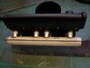
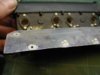
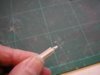
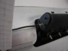
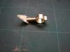
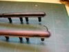
The cowlings are looking superb.

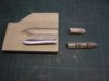
I'm sure on the full size aircraft the cowlings were also modified to fit. Even the car manufacturer Morgan has to tweak aluminium body panels to fit, the construction methods probably very similar to those used on vintage aircraft!

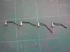
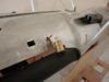
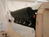
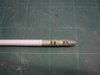
I'm looking forward to seeing how the wing mounted lewis gun turns out, with the curved track part which the gun moves along. All the attention to detail that you included in the cockpit that's going to make for a really interesting looking model.

I've never been a fan of the se5a in the past, with it's flat vertical front it's always looked a little pedestrian to me, on seeing one up close and from watching this thread though, I'm much more appreciative of the aircraft now.

One thing I never appreciated before was how central the cockpit is on this aircraft with the incredibly long nose forward of the wing, being an inline engine. It makes for a very balanced and elegant looking fuselage in profile. I've always been a fan of the Sopwith Pup and Camel, with their radial engines, have you considered modelling one of these? Litho plate for the bare metal cowls would look superb!
 
I'm coming to the point now where I have to stop talking about my own project and start some building. Your thread, Grahame, is just what I needed at this point: a veritable master class!!

It's a pity you hadn't time to build two, as I think that air museum curators would give their right arms to get their hands on a model of your making.
 
Thread owner
I was talking to a fellow scale modeller recently and discussing our differing ways of building; he likes to do all the construction first and then add details whereas I like to finish, as far as possible, each individual unit as I go along adding as much detail as is practical, of course we still end up with the same end product.


The exhaust starts life as simple tubes rolled from paper; a convenient thing about “rolling you own” is that it is easy to get the correct diameter, just keep adding extra turns until it’s right! I used watered down PVA glue this time and finished of with a coat of thinned shrinking dope.


View attachment 262773


Holes are drilled, slightly over sized, and the exhaust stubs glued in place with the unit fitted to the engine to ensure everything lines up, then any gaps filled. The rounded front is made from balsa.


View attachment 262774


Because the exhaust is round the flanges and holes aren’t; if you’re good at maths and familiar with radians you could produce a template but I found it easier to make a jig!


Luckily the front section of the exhaust is near enough 15mm diameter so a piece of copper pipe with a couple of holes does the job.


View attachment 262775


To make two flanges a strip of litho plate is wrapped around the pipe and held securely with Selotape then both holes carefully reamed out. With the litho plate removed any burrs are cleaned off, the rivets embossed and the outline drawn following the shape of the hole.
 

Attachments

  • exhaust 1.jpg
    exhaust 1.jpg
    1.8 KB · Views: 0
  • exhaust 3.jpg
    exhaust 3.jpg
    2.1 KB · Views: 0
  • exhaust 2.jpg
    exhaust 2.jpg
    1.9 KB · Views: 0
Grahame,I have always gone along with the idea that every small part is a model in itself,you obviously enjoy that same principle as well.

A lot of this intricate detail just cannot be added later anyway,especially as the structure is sealed up as major assemblies are built,also with these vintage subjects a lot of that character needs to be inbuilt along the way,your engine assembly is a good example of this.

Good old rolled paper tube is a wonderful way to achieve lightweight tubes,things are really working out well with your construction,I am sure that everyone here is learning something new with this build,after all it is very rare that we get such a wonderful insight into a modellers methods of construction,thank you.
 
Thread owner
I have encountered a problem with the rear exhaust pipes; I rolled them from paper as usual and left them overnight to dry but in the morning they were all bent. I’ve never had this trouble before but these are quite a bit longer, maybe that’s what caused it? I’ve done one leaving it on the former (an aluminium tube) overnight and that has stayed straight so that’s the way to do it, but of course it means I can only make one pipe per day and I need 4 altogether.


With the front exhaust section in position I can tell what detailing needs to be added to the engine; because the “normal” view will be looking down on the model, the spark plugs, which are hidden by the exhaust on the full size, are clearly visible. They are made from a 2mm nut, some plastic tube, a pin and a length of wire.


View attachment 262777


Being white they stand out quite clearly although the camera doesn’t show them as well as in real life!


View attachment 262778


Perhaps it’s the angle that I took the photo so here’s one without the exhaust in place that shows the finished effect much clearer.


View attachment 262779
 

Attachments

  • cowl 23.jpg
    cowl 23.jpg
    2.4 KB · Views: 0
  • cowl 22.jpg
    cowl 22.jpg
    2.2 KB · Views: 0
  • cowl 21.jpg
    cowl 21.jpg
    1.5 KB · Views: 0
Grahame the adhesive had probably not fully cured properly,thus the tube would distort as there would be moisture trapped on the inner layers of binding.

You have done the right thing by leaving them on the form to air dry naturally.

The engine parts look super.
 
Thread owner
The lower cowl is held in place by ¼ turn “buttons” that pass through slots, I've modelled these from plastic strip.


View attachment 262780


View attachment 262781


The model shop didn’t have any “X” section so I glued 2 “T” sections together then working with small files I shaped the fasteners.


They are pushed through the preformed slots in the cowl and secured from the back with a drop of thin cyano.


View attachment 262782


It’s all these little things that make cowls one of my favourite parts to make; they are so individual to each aircraft.
 

Attachments

  • cowl 28.jpg
    cowl 28.jpg
    2.3 KB · Views: 0
  • cowl 27.jpg
    cowl 27.jpg
    1.5 KB · Views: 0
  • cowl 26.jpg
    cowl 26.jpg
    1.9 KB · Views: 0
Grahame,they are called 'Zeus fasteners' common even today on modern aircraft cowlings and panels,once again the test of time shows that original ideas work best.
 
They were also used a lot on British motorcycles in the 50's and 60's. I once made one in a ships workshop from scratch to replace one lost from a BSA side panel.

I got it plated and it worked perfectly.
 
Thread owner
The engine detailing is now finished; the SE5a had most of it’s engine inside the cowl so there’s no a lot to see!


On both sides at the front there’s a copper oil pipe with a large brass fitting.


View attachment 262783


On the left there’s this, (no idea what it does but it’s very prominent). It’s made from a cut down cartridge, in this case a 223, a nut, aluminium tube and copper wire.


View attachment 262784


Last but not least there’s the take off for the RPM gauge on the rear of the right rocker cover; the flexible drive is 22swg solid core copper wire wrapped with button thread.


View attachment 262785


Someone recently asked about methods for making corrugated hoses, can’t remember who; I’d never done this before but thinking about it, it would make quite realistic hoses, not true corrugated, it’s a spiral but it would take a very close look to notice the difference. By altering the size of the core and the binding you could produce any size hose you wanted.


Here’s a close up, a bit fuzzy but it shows the general effect.


(can't find this picture yet)
 

Attachments

  • cowl 31.jpg
    cowl 31.jpg
    1.8 KB · Views: 0
  • cowl 30.jpg
    cowl 30.jpg
    2.2 KB · Views: 0
  • cowl 29.jpg
    cowl 29.jpg
    2.1 KB · Views: 0
Just a guess Greyhead it could be a manifold pressure sensor (piston or diaphragm type), sending a signal to the manifold pressure gauge.

Being where it is it must be transmitting either a pressure or a temperature signal somewhere.
 
Thread owner
Richard

It’s actually connected to the rocker box so it could be a pump driven by the camshaft, as it would also be regulated by engine speed it could be something to do with the interrupt gear for the Vickers.

It would be interesting to know what it does just in case someone asks me when looking at the model. I’ll sound a bit of a dummy saying, “I’ve got no idea.”

Grahame
 
Thread owner
Whilst I’m sure that the SE5a wasn’t designed with the sole intention of making life difficult for future aeromodellers, at times it certainly seems that way! Most early aircraft would make do with a simple tube for the exhaust but not the SE5a!!


The end of the exhaust is quite a complex affair, the modelling of which involved a lot of “metal bashing” and the construction of a couple of jigs.


View attachment 262786


The end of the exhaust tube has also had to have some work done cutting apertures behind the louvers and holes and the litho plate will need to be faired in with cellulose stopper before painting.


View attachment 262787
 

Attachments

  • exhaust 6.jpg
    exhaust 6.jpg
    1.5 KB · Views: 0
  • exhaust 5.jpg
    exhaust 5.jpg
    1.8 KB · Views: 0
Thread owner
The full size exhausts are in 3 sections, the front, which consists of the exhaust stubs and collector, the middle section is a straight pipe and then the rear section. I’ve left the model exhausts in 2 sections, at least for now as I work on the brackets.


View attachment 262788


A coat of silver Solarlac shows up any areas that need more filling, especially where the litho plate joins the rolled paper tube. It may seem strange to go to all this trouble to get a good finish when we want to end up with a pitted “rusty” finish but it is a lot easier to get the right effect starting from a consistent surface.
 

Attachments

  • exhaust 7.jpg
    exhaust 7.jpg
    2.2 KB · Views: 0
Terrific workmanship on the tails of those exhaust pipes, they should look the business when painted up. They are a really distinctive part of the SE5A too.
 
Don't why i have never looked at this thread of yours Greyhead but i have just gone from the beginning to the end and i must say this is one of the best stretch built models i have ever seen,so keep up the super work Greyhead and i am looking forward to seeing the finished plane in all it's Glory.
 
Thread owner
The front exhaust brackets are very substantial units, but then they need to be, there’s a good length of exhaust pipe to support on the SE5a. I soldered them up from brass tube, squeezed in the vice to make it streamlined section, and brass sheet.


View attachment 262789


When the bracket is fitted permanently the bolts will protrude from the fuselage so that the nuts are on the outside and obviously the pinch bolt will be cut down to size.


View attachment 262790


My idea at the moment is for the exhaust complete with brackets to be attached to the engine, which is attached to the lower cowl sides, thereby making the whole unit removable. The rear brackets are a bit of a problem because they aren’t bolted on from the outside, they will have to be made as 2 parts, the arms, attached permanently to the fuselage will plug into the exhaust pipe, I hope!
 

Attachments

  • exhaust 9.JPG
    exhaust 9.JPG
    2.2 KB · Views: 0
  • exhaust 8.jpg
    exhaust 8.jpg
    1.6 KB · Views: 0
Thread owner
The next job on the exhaust pipes is to give them an all over covering with a mixture of epoxy and micro balloons; this gives a rough pitted surface ready for painting. The layer of epoxy / micro balloons only needs to be very thin, I find it’s best to spread it with my finger, messy but effective.


When the epoxy has cured, it takes quite a while being such a thin layer, paint all over matt black. This isn’t the final colour, it’s just to make the “rust” less uniform and it also needs to be applied very sparingly, we don’t want any of the pits filled in.


A photo showing one exhaust matt black the other with its coat of “rust”, which is far more varied in colour than is evident from the photo.


View attachment 262791


On exhausts that are more than just stubs the rust usually follows a distinctive pattern so the rust is painted to reflect this, there is very little rusting in front of the exhaust stubs.
 

Attachments

  • exhaust 10.jpg
    exhaust 10.jpg
    2.3 KB · Views: 0
Status
Not open for further replies.
Back
Top