Theme editor

Scale Model Shop

SE5a CONSTRUCTION BEGINNING TO . . .

Status
Not open for further replies.
Thread owner
When I went the next morning to continue with the wheels I found that the covering had slackened off. I thought this was probably caused by using too much heat to shrink the Solartex; the correct method for complex curves is to apply a little heat, which makes the Solartex pliable, do most of the forming by actually stretching not shrinking, then use a bit more heat for final shrinking, if you use too much heat, the Solartex shrinks OK but after a while it “relaxes”.

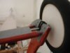
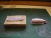
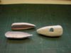
With the tyre in place I couldn’t pull the Solartex around the rim so I’d had to use a lot of shrinkage to get the fabric taut; I first made a jig so that I could pre-form the Solartex into a conical shape by stretching, stick it to the wheel then use heat for the final shrinking. The amount of heat needed to get the required shrinkage didn’t seem excessive although I still couldn’t get the Solartex onto the wheel really tight but after a few hours the Solartex was loose again.

For the next attempt I was going to have to remove the tyre, no easy feat with Williams Brothers wheels as they have a moulded lip that presses into a slot, I had to cut off a section of the lip to start with then pull extremely hard to remove the tyre. With the tyre removed I could stretch the Solartex around the rim and as an added bonus there was all the inside of the rim to attach the Solartex to so no chance of the bonding failing, the fabric was tightened using very little heat. After covering the back and struggling to get the tyre back on I went to bed a happy bunny!

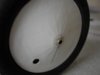
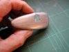
The next morning I wasn’t so happy; the covering was loose again, even the back which is virtually a flat disc; this called for drastic action! I tightened the Solartex again with the heat gun, poured some cyano on, spread it around evenly and gave it a blast of activator. I repeated this 3 times, the covering now feels quite solid and it appears to be remaining taut, but I’m not “counting any chickens” just yet!

With the back going slack all I can think of is that it must be some reaction between the covering and the plastic that the wheels are made of causing the Solartex to “relax”, has any one else had this problem?
 
Thread owner
Well the covering’s still tight this morning so hopefully that’s that problem solved, I just wish I knew what caused it in the first place!
 
Thread owner
The wheels have a plastic washer glued to both sides of the hub to protect the Solartex and to make the wheel attachment look more authentic the piano wire axle has brass tube sleeves added. To ensure a slop free fit I cut “teeth” in the end of the tube using the Dremmel and a cutting disc then reamed out the wheel holes with it.


View attachment 262843


The sleeves have a hole drilled for a split pin then a washer is soldered to form a “back stop”. A useful tip is to use a wooden spring type clothes peg to hold the washer square on the tube whilst soldering.


View attachment 262844


The sleeves are then glued to the piano wire axle with epoxy. The completed axle is held in position on the undercarriage with “O rings” to provide a certain degree of springing.


View attachment 262845


As you can see the spoke detail is very subtle just as per the full size, on most commercial wheels it is usually a bit “over done”.


View attachment 262846


I’ve had fellow modellers ask me why I don’t solder the tubes to the axle, well the simple answer is “It’s easier to use epoxy” and all I can say is that I’ve not lost a wheel yet, at least not one that was attached using this method!
 

Attachments

  • wheels 5.jpg
    wheels 5.jpg
    2 KB · Views: 0
  • wheels 8.jpg
    wheels 8.jpg
    1.6 KB · Views: 0
  • wheels 7.jpg
    wheels 7.jpg
    2.2 KB · Views: 0
  • wheels 6.jpg
    wheels 6.jpg
    1.7 KB · Views: 0
Solartex can be funny stuff at times,you could have had a slightly faulty batch it is possible,there is a built in shrinkage memory,although I have never used a themometer ever on any heat shrink material apparently you should do so according to Mr Hardiman its inventor,it probably is possible to over-stretch the material ? but who is bothered as your wheels look just like they did in WW.1,ie wrinkled slightly through constant canvas removal.
 
Thread owner
I’ve used the particular batch of Solartex before without any problems; I used “old stock” because I wanted to make sure that the spoke detail was correct, with natural Solartex being translucent it’s difficult to know exactly how it will look when it’s been painted. When I formed it into a conical shape on the jig I left it for a couple of hours to see if it would slacken off but it didn’t, until I attached it to the wheel that is, when it was obvious within a few minutes that it wasn’t going to be any good!

I’ve got a thermometer, which I used to check the temperature of the iron as per the instructions supplied with the Solartex, and marked my variable power supply accordingly but unfortunately I had to use a heat gun for the wheels, which is either on or off, having said that I’ve never had any problems using it in the past.
 
Thread owner
As I said earlier I intend to use the scale closed loop system for the aileron control and have been giving it some thought over the last few months; here are the results of my deliberations so far and any comments and / or suggestions will be gratefully received.


I can see 2 main areas of concern; firstly the servo will have to pull all 4 ailerons with their associated friction and aerodynamic forces. Even though I’ll be using 2 servos, one will have to pull all 4 ailerons to bank left and the other one will have to pull all 4 ailerons to bank right. Secondly the cables may jump off the pulleys if there is any slack in the system.


The first concern is easily, if not cheaply overcome. I will use “high torque” servos such as Futaba 3010 and a 6-volt battery pack; it’s the second concern that has been taxing the old grey matter!


In a perfect world both servos would move the same amount and there would be no slack, but in the real world, using the differential mix, the servos will have to be set such that the “pull” servo moves less that the “release” servo to ensure that they are not stalled by working against each other but this obviously introduces the “slack in the system” that I want to avoid.


Below is a sketch of the linkage I’ve designed which I hope will alleviate the problem, I will be making a test rig before I commit it to the model so please get your suggestions in quick before I start!


View attachment 262847


This is how I hope it will work.


To connect the aileron cables the spring is removed and both servo arms and rods moved out allowing plenty of slack to connect the “quick links”, the servos are then moved back to neutral to take up the slack and the spring replaced.


To bank to the left the right servo pulls the bottom right aileron down working against the aerodynamic force, which will keep the cable tensioned, the top aileron is pulled down by a cable between the right ailerons and similarly aerodynamic force will keep the cable tensioned. A cable, via control horns protruding from the upper surfaces, connects the 2 top ailerons so the left ailerons are pulled up and again aerodynamic force will keep the cables tensioned. The cable from the bottom left aileron to the left servo is where the problem arises, here the aerodynamic force, which up until now has taken up any slack, will actually transfer all the slack to this cable run. Added to this, as explained earlier, the left servo has “released” more cable that the right servo has pulled, but because the rod can slide through the servo arm connector the spring will now take up the slack keeping the cable itself tensioned into the pulley.


That’s the theory anyway!
 

Attachments

  • aileron linkage ).jpg
    aileron linkage ).jpg
    1.7 KB · Views: 0
It is a clever system Grahame but why not use two servos mounted in each wing to drive the coupled upper and lower ailerons ? this will eliminate any slop allowing a more direct linkage,you can lead cables through the ribs down to a 'Y' lead,you may have reasons not to want this type of layout but it is worth consideration,especially in view of the powerful smaller servos available today.

A small inspection plate or similar ensures that you can gain access to the link and servo maintenance itself.
 
This is a novel idea Grahame but I cannot visualise how it could work properly. For the spring to contract to take up any slack in the loop it must pull one, or both, servos from their true position as demanded by the control system. This would lead to the servo(s) ‘hunting’, I’m not sure if this would cause any damage apart from the extra drain on the battery but I doubt it is a good situation to build into a system.

An alternative would be to only use a single servo and incorporate a spring in the loop, it would have to be sufficiently strong to counter the aerodynamic loads on the ailerons, however the use of springs without damping in any control system is prone to oscillation and would possibly (likely?) lead to aileron flutter – not a good thing.

My thoughts were along the same lines as Barry’s but one step further and that is to use a servo for each aileron and have the cable control system just for show, the same idea as you are going to use for the elevator, this loop could then have springs in it to take up any slack with no adverse side effects that I can see, this would give good positive control of each aileron.

Hitec do some nice servos specifically designed to fit into a thin wing but with plenty of torque. The down side would be the hole it would leave in your pocket – I know as I’ve just bought a pair for a high performance electric soarer I built over the winter.
 
Thread owner
Thank you for the comments and suggestions, I’ll leave it a couple of days in case there are any more then reply to them all in one go.


Today I’ve made these, 4 in all, from plastic tube, washers, pins and copper wire.


View attachment 262848


They are attached to the inlet manifold so I think they are for injecting neat petrol into the engine during start up. Whatever they’re for they fill up the 4 holes in the cowl quite nicely!


View attachment 262849


The trouble is they appear to hanging in mid air, I might have to add the inlet manifolds to the engine; one job just leads to another!
 

Attachments

  • cowl 33.jpg
    cowl 33.jpg
    2.3 KB · Views: 0
  • cowl 32.jpg
    cowl 32.jpg
    2.1 KB · Views: 0
Grahame, one concern with your proposed arrangement is that you are inducing a torque, all be it via a spring into the resting servo. This is going to cause the servo to work to maintain position, which it will do but it will be using battery power to acheive this.

Although I see your idea working I think it will be heavy on battery use so I would undertake some very thorough and lengthy bench testing before committing to your arrangement.
 
I've just had another look at your diagram for the aileron closed loop system and realised that I had somewhat misunderstood it in that the bushes are not fixed to the actuating rods but are free to slide. This would certainly reduce the chance of stalling one or both of the servos but whether it would totally stop it would, I think, have to be a build it and see exercise.

The servo I was talking about was the Hitec HS-125 BB which is only 10mm thick with obviously a bit more for the arm. Spec and picture at http://www.servoshop.co.uk/index.php?pid=HITHS125MG&area=Servo&PHPSESSID=d1d18a1020fd37c8d62c9a20bf255a40
 
Thread owner
My starting point for the aileron control is that I’d like to use the scale closed loop system if at all possible because: it’s scale, I like a challenge and, considering that the pulleys etc will have to be included for scale fidelity anyway, if it works my proposed system will be easier to implement. So onto your comments, I probably didn’t explain it fully enough in the first instance but I think David now has the idea.

The rods are not attached solidly to the servo arms but are free to slide through the holes in the connectors, when one servo moves towards the centre it pulls the rod because the connector is in contact with the spring attachment hook, this in turns pulls all 4 ailerons in the desired direction. The other servo moves outwards to “release” the cable but doesn’t actually push the rod; if there is any slack then the spring can pull the rod back through the servo connector. In practice I will ensure that there is always some slack by using the differential mix. The spring tension will not be imparted to the servos but will keep the cable tight into the pulleys, I hope!

The possibility of aileron flutter is something I hadn’t considered, but thinking about it now as far as I can see the spring will only have any effect on the cable run from the last bottom aileron to the servo. When setting up a closed loop system using the Ackerman principle, the “released” cabled actually goes slightly slack and this doesn’t cause any problems so a bit of oscillation in this cable run shouldn’t cause too much trouble. Without having access to a wind tunnel I’ll just have to chance it!

If my system proves not to work I will have to use individual servos in the wings; if to scale the wire joining the top and bottom ailerons will be too thin to use as a push rod so it’s either non scale joining wire or use a separate servo for each aileron, in either case space is a problem. The wing section is very thin; in practical terms I only have about 16mm in which to fit the servo and arm and I’m not sure I could get sufficient throw, especially as the aileron control horns are 23mm long, even using those very thin Hitech servos. I could possibly use the “bent rod and slot” method as used on scale models when the full size has hidden control horns but that’s a method I’ve never used before so would require some experimentation.

Once again thanks for your input, time to start experimenting I think!
 
Thread owner
The 2 fairings that cover the bungee cord used for springing on the axle will have to be hollow mouldings and they will have to be made in 2 halves so that involves making 4 identical pieces; I think a mould is called for!


First a plug is made from balsa, given a few coats of sanding sealer to produce a smooth surface and a box built around it.


View attachment 262850


Mould making rubber, a very soft material that melts at a relatively low temperature, is heated over the gas ring and poured into the box to produce the finished mould. The good thing about this material is that when you’re finished with the mould you just melt it down and use it again.


View attachment 262851


I really don’t like fibreglass / resin moulding so following Barry’s suggestion I tried paper and watered down PVA glue. To get the paper to conform to the shape I had to cut it into strips, it was thoroughly soaked in the glue then 3 layers applied in herringbone fashion. I was surprised just how quickly it set, it can be removed from the mould in a couple of hours and although not thoroughly dry it holds the shape.


View attachment 262852


This was my first attempt; I did things slightly differently for the subsequent mouldings in that I tore the paper into strips rather than cut it and I made doubly sure there were no air pockets under the first layer before proceeding with the second. This first attempt has been scrapped but shows up the herringbone pattern well, using the torn paper the joins are a lot less evident.
 

Attachments

  • wheels 11.jpg
    wheels 11.jpg
    2.1 KB · Views: 0
  • wheels 10.jpg
    wheels 10.jpg
    1.9 KB · Views: 0
  • wheels 9.jpg
    wheels 9.jpg
    2.1 KB · Views: 0
Thread owner
Making these paper mouldings has been a bit of a steep learning curve for me, I think it is really more suited to covering the outside of a shaped form rather than using a female mould as I’ve done, but I have to say I’m happy with the results, which are both light and sufficiently strong. After the pieces had dried overnight the edges had deformed somewhat becoming concave; this was easily remedied by holding them in the correct shape with a balsa template and then heating with the hot air gun, this softened the glue which then hardened and held the correct shape.


As I’m just learning this technique I decided to work on one fairing before I started on the second.


View attachment 262853


I wasn’t sure if the fairing would fit in one piece, as it does, or have to be left as separate halves, so I did the trimming to fit before joining them, which made things a bit more awkward; hopefully the second will be easier. Once again I’m not trying of a perfect finish, being in such a vulnerable position I’m certain they soon ended up with a considerable number of dents and scratches.
 

Attachments

  • wheels 12.jpg
    wheels 12.jpg
    1.9 KB · Views: 0
For a first attempt Grahame they look fine to me. I always find it interesting to see what new techniques you are going to come up with to tackle a specific challenge.
 
Have often thought of trying that rubber moulding material Grahame,did you get it from Alex Tiranti ?
 
Just wondering,

I am sure a home built VacForm Mould would have done this nicely and a lot less messy too...just another suggestion.

I have one of these and it just plugs into a standard Hoover to do the Vac Forming when required.

I bought a basic kit one from the old MAP Plans service years ago and eventually finished it for use, great easy tool to use. Very Cheap to construct from scratch too.

Regards...Mark.
 
Thread owner
Richard


You never stop learning in this game!


Barry


I bought the “moulding rubber” some years ago from my local model shop; I originally used it to make rubber mountings at the wheel spats to wing joint on a Stuka. As with most things it has more uses than the one it was designed for.


Mark


A vac-forming machine sounds like a worthwhile investment at that price (very cheap!!), any chance of uploading a sketch with sizes / materials used etc.; daren’t ask for a “scan”, that would really upset John!


Grahame


When cutting out the clearance holes for the undercarriage legs it became clear that the thickness of the mouldings wasn’t very even to say the least; I’d obviously used less layers of paper in some places, so for my next attempt I’ll use alternating layers of white and coloured paper, this should even things up.


The “join” is simulated using litho plate embossed with a row rivets and a row of screws, faired in with cellulose stopper. At first I tried using just one strip with both rows embossed and a score line down the middle but I couldn’t form it around the fairing without loosing a lot of the embossed detail, so I used 2 separate strips; this has actually worked out better in the end because the “join” now isn’t perfect, just as the full size. The finished fairings are painted with silver Solarlac so that they will appear to be metal when the PC10 is weathered.


View attachment 262854


I’m not too happy with the embossed screw detail but at the moment everything is silver, maybe it’ll look better when it’s coloured and weathered, if not I’m sure I’ll be able to think of some way to improve matters.
 

Attachments

  • wheels 13.jpg
    wheels 13.jpg
    2.2 KB · Views: 0
Thread owner
I’ve made a test rig to check my idea for the aileron linkage.


View attachment 262868


The hinge point for the top lever is such that there is “built in” slack in the system as it moves from the neutral position; the spring is provided by a rubber band.


This is a photo of the left hand servo after it has pulled the cable; I’ve marked the rod at the contact point with the servo connector.


View attachment 262869


And this is a photo of the same servo after the right hand servo has pulled the cable; the rubber band has taken up the slack as evident by the mark on the rod. Of course the exact opposite happens with the other servo


View attachment 262870


The system certainly works, keeping tension in the cable, I’m sure it will work a lot better when I’ve made a proper engineering job of the actuating rods and the sliding bearings.
 

Attachments

  • aileron linkage2.jpg
    aileron linkage2.jpg
    2.4 KB · Views: 0
  • aileron linkage1.jpg
    aileron linkage1.jpg
    2 KB · Views: 0
  • aileron linkage3.jpg
    aileron linkage3.jpg
    2 KB · Views: 0
Status
Not open for further replies.
Back
Top