Theme editor

Scale Model Shop

Wonwings Diary-a blog with a difference.

Status
Not open for further replies.
Barry, I just want to say how good it is to have you back again. We've missed the aircraft history input that was always so enjoyable to read so i'm really glad to see you contributing again.

Fantastic project in the shed! Will you be building it to an airworthy standard or just as a static aircraft? Either way it is going to loom pretty amazing.

Looking forward to your contributions again, and again good to see you back.
 
Thread owner
Thank you Richard for the warm welcome,it is good to be back talking about the things we enjoy doing most and the absence was only a temporary thing really,sometimes we have things happen in our lives that change the way we think,well I certainly did,a years intensive training courses and a few health issues and scares as well thrown in,but hey we are still here to moan ! here are a few more pictures of the Tawney Owl with the cockpit skinning in place now wrapped up until the Spring when the booms will be built and mated to the tailplane,meanwhile I need to draw up the fin/rudder assemblies and replicate these from a single structural member that I have of them,after a lot of intense activity on the airframe time to take a break and get some model building done again.

She will not fly as that is one of the stipulations,however the build is to a high standard and the aircraft would easily taxy should I find a suiable engine,once finished the aircraft is destined for an air museum and something else will take her place in the workshop.

Barry.
 
Thread owner
Building a Miles Gemini

There are so many aircraft types that will never be made commercially as models,even if they did appear as resin castings or Vac Forms they would be very expensive as they are produced by cottage industries in very small numbers.

I prefer to make these types from wood and other scrap material that I have to hand,firstly a drawing is prepared to the size that I need then suitable wood is utilised to fit the card patterns that are made from the plans.

Each component is broken down into sections ie main fuselage,wings,tail,undercarriage,propellers and any other items that go into the construction of the particular model,after a while and a few models have been built you tend to develop a style of building that suits yourself,I like to make myself a set of parts all sanded and trimmed neatly ready for assembly,this way I can sweep up the dust and settle into the build itself which I find relaxing and very enjoyable,once the parts are trimmed it is sometimes necessary to make up simple jigs to hold things in place,these need not be elaborate but simply cardboard from cereal boxes cut and folded into rests and supports,you will find that biplane models in particular need this necessary jigging to assist in lining up the wings in relation to the fuselage,then after this has been completed and the adhesive has cured the various struts and fittings can be added.

Over the coming weeks and months I will be dealing with different models that have been constructed together with the various techniques used,for anyone who has not tried scratch building then I can highly recommend the satisfaction derived from creating something from the ground up,the models become unique pieces in themselves and present challenges that keep the mind active.

So here we have the Miles Gemini a popular post war touring aeroplane that was especially used for air racing by its owners,the aircraft was comfortable to fly and had very nicely balanced controls,the model brings out the lines of this classic machine.

Wonwinglo.

View attachment 27824

View attachment 27825

View attachment 140350

View attachment 140351
 

Attachments

  • MILES GEMINI ASSEMBLED.jpg
    MILES GEMINI ASSEMBLED.jpg
    2.7 KB · Views: 0
  • MILES GEMINI MAJOR PARTS.jpg
    MILES GEMINI MAJOR PARTS.jpg
    2.8 KB · Views: 0
Thread owner
Building the DH.90 Dragonfly 1930's private owner twin engined biplane.

View attachment 20833

This attractive pre war twin engined biplane lends itself well to building a miniature model,the picture above shows the first one that was made many years ago to 1=72nd scale and prompted me to build a much larger model of this fine aircraft.

For scaling up I usually work out the sizes on my computer screen working out the wingspan etc between two marks in something like a word programme,the beauty of this system is that it enables you to scale exactly and easily,the next step is to transfer the drawings onto card for the essential templates,not only can these be used to draw the respective shapes around but also as a constant guide during assembly,even to the very end when you need to transfer things like ailerons,control surface detail etc the humble card templates are there,and sure they can later be filed away in plastic folders together with the plans and templates forming a file for future builds or rebuilds.

One very important area of construction lies with the setting of the dihedral angle of the wings,to achieve this I cut halfway through the wood with a razor saw and then take a Swiss file with a 'V' edge to carefully open the joint,then two blocks of wood are positioned at the wingtips and the centre section is pinned down,then a thin line of cyno is run into the joint to lock it into place,once this is dry then a fine application of Squadron white filler is smoothed into the join line,allowed to dry and carefully sanded down with strips of masking tape either side to protect the material being sanded.

The photographs serve to show a typical assembly sequence of a twin engined aircraft,done this way a careful eye can be kept on symmetry.

Once everything is fixed in place the next stage will be dealt with later,watch this space.

Wonwinglo.

View attachment 27827

View attachment 27828

View attachment 27829

View attachment 27830

View attachment 27831

View attachment 27832

View attachment 27833

View attachment 27834

View attachment 27835

View attachment 27836

View attachment 27837

View attachment 27838

View attachment 27839

View attachment 27840

View attachment 27841

View attachment 27842

View attachment 27843

View attachment 140353

View attachment 140354

View attachment 140355

View attachment 140356

View attachment 140357

View attachment 140358

View attachment 140359

View attachment 140360

View attachment 140361

View attachment 140362

View attachment 140363

View attachment 140364

View attachment 140365

View attachment 140366

View attachment 140367

View attachment 140368

View attachment 140369
 

Attachments

  • DH90#11.jpg
    DH90#11.jpg
    2.5 KB · Views: 0
  • DH90#3.jpg
    DH90#3.jpg
    2.6 KB · Views: 0
  • DH90#6.jpg
    DH90#6.jpg
    2.6 KB · Views: 0
  • DH90#10.jpg
    DH90#10.jpg
    2.7 KB · Views: 0
  • DH90#13.jpg
    DH90#13.jpg
    2.6 KB · Views: 0
  • DH90#12.jpg
    DH90#12.jpg
    2.8 KB · Views: 0
  • FOKKER D7#1.jpg
    FOKKER D7#1.jpg
    2.9 KB · Views: 0
  • DH90#14.jpg
    DH90#14.jpg
    2.6 KB · Views: 0
  • DH90#1.jpg
    DH90#1.jpg
    2.4 KB · Views: 0
  • 1414b5d30.jpg
    1414b5d30.jpg
    1.8 KB · Views: 0
  • 144e71e30.jpg
    144e71e30.jpg
    2.2 KB · Views: 0
  • DH90#4.jpg
    DH90#4.jpg
    2.5 KB · Views: 0
  • H90#8.jpg
    H90#8.jpg
    2.7 KB · Views: 0
  • DH90#5.jpg
    DH90#5.jpg
    2.4 KB · Views: 0
  • DH90#7.jpg
    DH90#7.jpg
    2.6 KB · Views: 0
  • DH90#2.jpg
    DH90#2.jpg
    2.7 KB · Views: 0
  • DH90#9.jpg
    DH90#9.jpg
    2.5 KB · Views: 0
Thread owner
The Miles Whitney Straight

This model of the Miles Whitney Straight combines two of my passions,firstly my love of vintage aeroplanes and secondly the joy of scratchbuilding which is the way that I build most of my models.

The model came about the plan to build as many different Miles machines as I could to fit into the collection,the Miles company produced a whole series of light touring aeroplanes both pre and post war pioneering moulded plywood construction in their construction which produced a fine surface finish for good performance in the air.

These machines were mainly of the tandem open-cockpit variety, similar in arrangement to the early Hawk monoplanes, and it was not until 1936 that the class neared an ideal in the Miles Whitney Straight side-by-side cabin monoplane. This aeroplane was the result of collaboration between the wealthy aviation enthusiast Mr. Whitney Straight, who then operated a series of flying clubs in various parts of the country, and Mr. Miles, both having almost identical ideas on the form of a modern light aeroplane.

The prototype Whitney Straight (G-AECT) first flown on 14th May 1936 and its all-round good qualities exceeded expectations, comfortable and easy to fly, with a top speed of 145 mph. and a fuel consumption of over 20 miles to the gallon. Immediate production followed the successful flight tests, and 50 M.11A, M.11B and M.11C aircraft were sold in almost every part of the world over the next two years. A number of these were used for experimental purposes, including the testing of various engines and, on the prototype, of auxiliary aerofoil flaps, the data gained proving beneficial to later Miles aircraft. A later model, known as the M.11 C, was fitted with the Gipsy Major Series II engine and a variable pitch airscrew, this combination giving a remarkable take-off and climb performance.

Perhaps one of the finest demonstrations of the all-round handling qualities of the machine was provided by the result of the 1937 King's Cup Air Race, in which General Lewin, then aged sixty-three, flew his own Whitney Straight into second place after a very close contest.

On the outbreak of war, in 1939, most of the Whitney Straights in Britain were requisitioned for R.A.F. communication duties, including 23 for the RAF (21 in the UK and two in India), and three for the Royal New Zealand Air Force. Many were still giving good and faithful service after five arduous years.

An improved model of the M.11 was developed with three-seat accommodation and flown as the M.17 Monarch on 21st February 1938.

The model follows the time tested tecnique of balsa wood for the basic components with pattern makers artificial wood being used to carve the delicate whell spats,the finish was achieved with sanding sealer a mix of clear dope and talcum powder and several sprayed coats of good old Halfords grey auto primer which I purchase six cans at a time ! a light rub down between coats and checking for blemishes which are rectified with Squadron model filler applied with a dental tool into the tiny crevices that seem to show up like a sore thumb once that primer is in place.

For the final finish I choose a warm day to avoid blooming of the acrylic paint also rattle can colours.

For the registrations and fine details I paint by hand steadying my hand against the workbench and use a small strip of wood or old paintbrush handle to paint the straight lines.

The realistic in flight flying propellers can be made from clear plastic discs cut from cosmetic boxes,these look good when the model is hung from the ceiling in flying attitude.

Wonwinglo.

View attachment 20985

The next Miles machine to be built after the Whitney Straight will be the Miles Mohawk which will be dealt with in another posting,the aircraft which is now in the RAF Museum was specially built for Colonel Charles Lindbergh.

( Click onto the pictures for larger images )

View attachment 27962

View attachment 27963

View attachment 27964

View attachment 27965

View attachment 27966

View attachment 27967

View attachment 27968

View attachment 27969

View attachment 27970

View attachment 27971

View attachment 27986

View attachment 140488

View attachment 140489

View attachment 140490

View attachment 140491

View attachment 140492

View attachment 140493

View attachment 140494

View attachment 140495

View attachment 140496

View attachment 140497

View attachment 140512
 

Attachments

  • WHITNEY STRAIGHT COMPLETED#2.jpg
    WHITNEY STRAIGHT COMPLETED#2.jpg
    2.9 KB · Views: 0
  • WHITNEY STRAIGHT COMPLETED#6.jpg
    WHITNEY STRAIGHT COMPLETED#6.jpg
    2.4 KB · Views: 0
  • WHITNEY STRAIGHT COMPLETED#4.jpg
    WHITNEY STRAIGHT COMPLETED#4.jpg
    2.9 KB · Views: 0
  • WHITNEY STRAIGHT COMPLETED#5.jpg
    WHITNEY STRAIGHT COMPLETED#5.jpg
    3.2 KB · Views: 0
  • WHITNEY STRAIGHT COMPLETED#7.jpg
    WHITNEY STRAIGHT COMPLETED#7.jpg
    2.3 KB · Views: 0
  • WHITNEY STRAIGHT COMPLETED#1.jpg
    WHITNEY STRAIGHT COMPLETED#1.jpg
    2.6 KB · Views: 0
  • WHITNEY STRAIGHT COMPLETED#8.jpg
    WHITNEY STRAIGHT COMPLETED#8.jpg
    3.4 KB · Views: 0
  • WHITNEY STRAIGHT COMPLETED#3.jpg
    WHITNEY STRAIGHT COMPLETED#3.jpg
    2.5 KB · Views: 0
  • new_MOHAWK DEF LABEL.jpg
    new_MOHAWK DEF LABEL.jpg
    3.2 KB · Views: 0
  • MILES WHITNEY STRAIGHT.jpg
    MILES WHITNEY STRAIGHT.jpg
    2.5 KB · Views: 0
  • MILES WHITNEY STRAIGHT#.jpg
    MILES WHITNEY STRAIGHT#.jpg
    3 KB · Views: 0
Thread owner
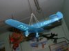
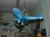
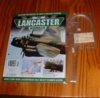
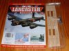
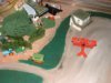
Partworks Avro Lancaster-Building the wing roots in Part 20

View attachment 20995

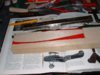
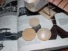
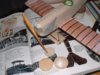
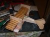
Part 20 includes the following parts for this assembly-

Wing root ribs for the section just aft of the wings,quantity 2.

A flat pack of plastic stringers to add to this assembly.

Another pack of stringers curved up into the magazine which were missing

from Issue 14 for adding to the centre section module.

Stickers for representing the Gas detection panels on the front and rear of

the pilots seat.

Method-

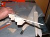
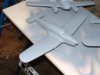
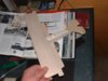
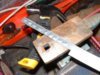
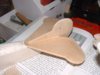
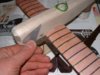
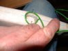
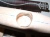
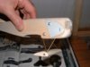
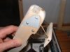
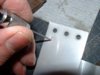
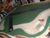
Remove the root ribs carefully from the fret,now take the portion of the

fuselage which is the immediate aft section where it meets the

wings,carefully click these part ribs into place on the protuding portions

of the formers,exercise care as any undue pressure will break the formers

especially the portions that hang down,once this is wriggled into place

check to make sure that it sits flush with the formers,if you are a bit out

with your formers then now is the time it shows up and you may need to trim

a little,next take the assembly outside in the fresh air and flood the

joints with thin cyno where the rib portion meets the formers,there will be

a short puff of smoke as the cyno cures against the dusty wood,thats the

reason for doing this job outside ! I chose cyno for two reasons,one its

strength in this critical area of the model,and also it is easier assembling

dry than fiddling with wet adhesive in this awkward assembly,you will see

what I mean once you offer it up.

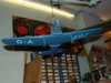
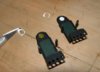
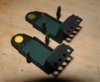
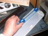
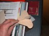
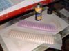
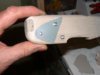
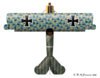
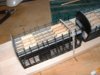
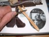
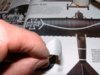
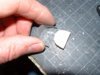
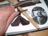
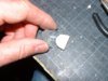
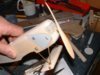
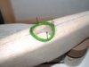
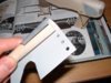
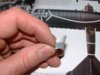
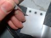
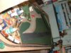
Now onto the seats,the Gas detection circles were to detect mustard gas

attacks,any presence of gas would discolour the discs alerting the crew to

danger as they donned their gas masks,the ones provided are vinyl stickers

with yellow print,if you place them onto the dark coloured seats then they

do not show up very well,what I did was to use the outer portion of the disc

as a stencil,I then applied a bit of white paint within the disc,then added

the vinyl sticker,look at the pictures and see the difference it makes as

the luminosity of the white paint shows through.
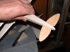
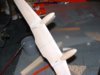
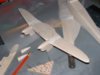
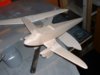
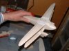
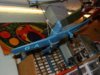
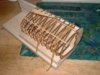
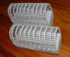
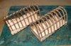
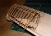
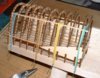
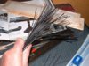
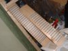
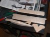
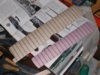
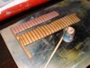
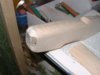
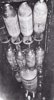
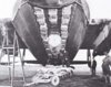
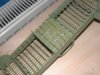
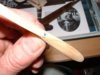
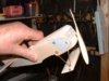
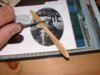
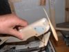
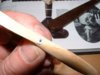
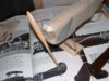
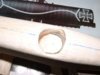
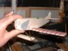
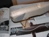
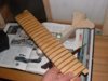
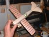
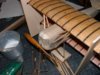
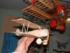
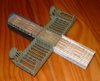
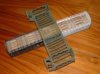
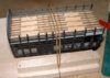
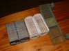
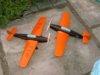
Stringers-

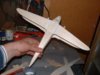
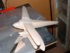
Next job is to add the stringers to the fuselage module,I wanted a better

method of doing this and decided to make a simple jig which not only makes

the job easier,but allows a much neater job.

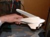
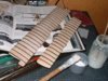
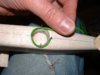
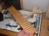
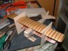
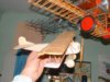
To make the jig is simple and you can use it on any parts of the models

fuselage structure during the build,take two pieces of balsa or similar and

butt one onto the end of the jig base ( see pictures for a beter idea of how

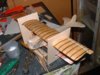
it is made ) all you do then is offer the fuselage portion into the

jig,place some weak elastic bands at strategic points to hold the stringers

flush as they are added to the assembly,you can move the module around as

you deal with each stringer until completed.

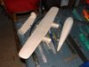
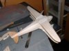
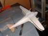
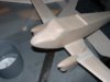
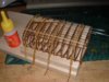
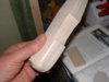
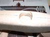
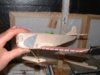
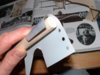
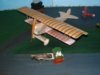
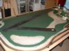
Allow this to cure out and then with your sanding block go all over the

outside blending everything in,the plastic sands well so do not be afraid to

do the sanding as it makes for a neat job,finish off with fine abrasive

paper,next sand the ends of the formers where they will butt up to the next

pieces eventually.

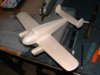
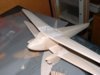
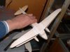
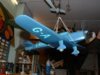
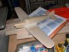
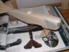
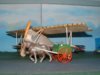
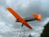
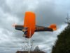
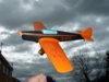
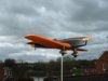
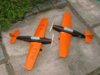
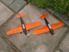
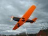
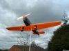
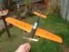
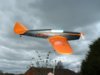
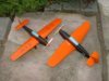
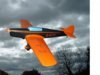
Now paint this portion with whatever scheme you are using,I have sprayed

mine white primer at this stage only because I need to get some grey primer

and some more Vauxhall Reed green paint to finish off the job.

The full build sequence for the partworks Avro Lancaster project can be found on the Google group build.

View attachment 27987

View attachment 27988

View attachment 27989

View attachment 27990

View attachment 27991

View attachment 27992

View attachment 27993

View attachment 27994

View attachment 27995

View attachment 27996

View attachment 140513

View attachment 140514

View attachment 140515

View attachment 140516

View attachment 140517

View attachment 140518

View attachment 140519

View attachment 140520

View attachment 140521

View attachment 140522
 

Attachments

  • new_PART 20 JUG FOR ADDING STRINGERS.jpg
    new_PART 20 JUG FOR ADDING STRINGERS.jpg
    2.8 KB · Views: 0
  • new_PART 20 PRIMERED.jpg
    new_PART 20 PRIMERED.jpg
    3 KB · Views: 0
  • new_PART 20 COVER.jpg
    new_PART 20 COVER.jpg
    3.5 KB · Views: 0
  • new_PART 20 SEAT GAS DETECTION DISCS.jpg
    new_PART 20 SEAT GAS DETECTION DISCS.jpg
    2.1 KB · Views: 0
  • new_PART 20 ADD THE ROOT FILLETS.jpg
    new_PART 20 ADD THE ROOT FILLETS.jpg
    3 KB · Views: 0
  • new_PART 20 SEAT GAS DETECTION DISCS#.jpg
    new_PART 20 SEAT GAS DETECTION DISCS#.jpg
    2.7 KB · Views: 0
  • new_PART 20 JIG FOR ADDING STRINGERS#.jpg
    new_PART 20 JIG FOR ADDING STRINGERS#.jpg
    2.4 KB · Views: 0
  • new_PART 20 JIG FOR ADDING STRINGERS DEF.jpg
    new_PART 20 JIG FOR ADDING STRINGERS DEF.jpg
    3.4 KB · Views: 0
  • new_PART 20 JIG FOR ADDING STRINGERS.jpg
    new_PART 20 JIG FOR ADDING STRINGERS.jpg
    2.6 KB · Views: 0
  • AVRO LANCASTER INTERNAL VIEW.jpg
    AVRO LANCASTER INTERNAL VIEW.jpg
    3.5 KB · Views: 0
Thread owner
Building a 1=24 th scale Fokker D7 from the film 'Hells Angel's'

This one is a bit out of the rut from the usual Fokker D7 schemes,it represents a Fokker D7 as used in the classic Howard Hughes film 'Hells Angel's' made in the roaring thirties,the aircraft was painted a pseudo black finish with white markings and looks very distinctive.

My models are made from scratch to traditional model building techniques,these carry on the traditions from before plastic models were thought of and I really enjoy using methods that have been passed down to me that although requiring more work than usual give great satisfaction both during the build and once completed and on display.

Here you see the basic parts have been cut and carved from medium grade balsawood,these are then sanded smooth with very fine sandpaper to a silky finish,the ribs on the Fokker D7 are represented with sugar paper glued into place onto the wings and then covered with model aeroplane tissue,this represents the sag in the ribs as per the full sized aircraft.

You can see the sugar paper being cut to width with a paper cutter,then a piece of wood is marked with the appropiate spacing with the wings attached via small rubber bands, then the strips are glued from the leading edge stretching to the trailing edge,they are then locked with thinned down PVA adhesive and once everything is dry the trailing edges will be scalloped with a half round file to represent the pulled in piano wire trailing edge created with the tautening dope.

As the model progresses more old techniques will be illustrated here.

Wonwinglo.

View attachment 28015

View attachment 28016

View attachment 28017

View attachment 28018

View attachment 28019

View attachment 28020

View attachment 28021

View attachment 140541

View attachment 140542

View attachment 140543

View attachment 140544

View attachment 140545

View attachment 140546

View attachment 140547
 

Attachments

  • FOKKER D7#5.JPG
    FOKKER D7#5.JPG
    2.6 KB · Views: 0
  • FOKKER D7#9.JPG
    FOKKER D7#9.JPG
    3.2 KB · Views: 0
  • FOKKER D7#14.JPG
    FOKKER D7#14.JPG
    3.3 KB · Views: 0
  • FOKKER D7#8.JPG
    FOKKER D7#8.JPG
    3.1 KB · Views: 0
  • FOKKER D7#10.JPG
    FOKKER D7#10.JPG
    2.7 KB · Views: 0
  • FOKKER D7#6.JPG
    FOKKER D7#6.JPG
    2.5 KB · Views: 0
  • FOKKER D7#1.JPG
    FOKKER D7#1.JPG
    2.8 KB · Views: 0
Thread owner
Aeroplanes worth modelling-The Breguet 14 French bomber.

The Breguet 14 was the French equivalent of our Bristol F2B Fighter,however the Breguet 14 was much heavier and looked stately in flight,here we have a real treat as a project to build and include some rare plans which are 90 years old to build it ! they came from a long defunct publication called 'Air Stories' which included every month a set of drawings to build a classic machine,you can build models from these plans and instructions just as you could then all those years ago,wood is still wood and provided that you take a bit of care then a successful model should turn out,enjoy a real vintage flying machine.

Wonwinglo.

View attachment 21021

View attachment 28022

View attachment 28023

View attachment 28024

View attachment 28025

View attachment 28026

View attachment 28027

View attachment 28028

View attachment 28029

View attachment 140548

View attachment 140549

View attachment 140550

View attachment 140551

View attachment 140552

View attachment 140553

View attachment 140554

View attachment 140555
 

Attachments

  • BREGUET BOMBER#1.jpg
    BREGUET BOMBER#1.jpg
    2 KB · Views: 0
  • breguet14 BOMBER.jpg
    breguet14 BOMBER.jpg
    1.7 KB · Views: 0
  • BREGUET BOMBER#3.jpg
    BREGUET BOMBER#3.jpg
    2.3 KB · Views: 0
  • BREGUET#5.jpg
    BREGUET#5.jpg
    2.1 KB · Views: 0
  • breguet-14.jpg
    breguet-14.jpg
    2.3 KB · Views: 0
  • BREGUET BOMBER#2.jpg
    BREGUET BOMBER#2.jpg
    2.3 KB · Views: 0
  • BREGUET#4.jpg
    BREGUET#4.jpg
    2.1 KB · Views: 0
  • BREGUET#6.jpg
    BREGUET#6.jpg
    2.3 KB · Views: 0
Thread owner
Building the Fokker D7

Today I produced some of the detailing around the engine area, and for this I used good old fashioned printers litho now difficult to get hold off due to the fact that it is not used much in the industry these days,the engine louvres were made by lightly stamping them from the rear onto a block of hardwood using a blunt small screw driver as the mandrel.

The tissue has been applied over the wing ribs and was applied using some Aldi spray adhesive from their bargain counter,wish now that I had brought more at a £1 a tin ! better than any 3m product as well at ten times the price.

Last job before I closed up the workshop for the night was a coat of clear dope over the Jap View attachment 21060tissue to tighten everything up,the fin is offset to the left to counteract engine torque as set up by the Fokker factory,the distinctive side panView attachment 21059el a feature of the D7 were also made from Litho after first cutting out a cereal box template and marking the positions.

Next job will be to makeView attachment 21058 up the undercarriage from brass tube and assemble the small stability wing between the wheels,plus to carve a distinctive propeller.

Wonwinglo.

View attachment 21057

View attachment 28055

View attachment 28056

View attachment 28057

View attachment 28058

View attachment 28059

View attachment 28060

View attachment 28061

View attachment 28062

View attachment 28063

View attachment 28064

View attachment 28065

View attachment 28066

View attachment 140581

View attachment 140582

View attachment 140583

View attachment 140584

View attachment 140585

View attachment 140586

View attachment 140587

View attachment 140588

View attachment 140589

View attachment 140590

View attachment 140591

View attachment 140592
 

Attachments

  • FD7#6.JPG
    FD7#6.JPG
    3.2 KB · Views: 0
  • FD7#8.JPG
    FD7#8.JPG
    3.6 KB · Views: 0
  • FD7#5.JPG
    FD7#5.JPG
    2.5 KB · Views: 0
  • FD7#14.JPG
    FD7#14.JPG
    3.2 KB · Views: 0
  • FD7#1.JPG
    FD7#1.JPG
    2.8 KB · Views: 0
  • FD7#3.JPG
    FD7#3.JPG
    2.4 KB · Views: 0
  • FD7#4.JPG
    FD7#4.JPG
    2.6 KB · Views: 0
  • FD7#10.JPG
    FD7#10.JPG
    2.4 KB · Views: 0
  • fokker-dvii-udet-top.jpg
    fokker-dvii-udet-top.jpg
    3.1 KB · Views: 0
  • fokker-dvii-friedrichs.jpg
    fokker-dvii-friedrichs.jpg
    1.9 KB · Views: 0
  • fokker-dvii-friedrichs-top.jpg
    fokker-dvii-friedrichs-top.jpg
    2.6 KB · Views: 0
  • fokker-dvii-udet.jpg
    fokker-dvii-udet.jpg
    2.2 KB · Views: 0
Thread owner
Aeroplanes worth modelling-The Vickers Supermarine Spitfire 1

These old plans from the pulp magazine 'Air Stories' are excellent despite their age,they represent the Spitfire 1 with wooden propeeler and faired in cockpit which make this early Spitfire so distinctive.

The draughtsman is James Hay Stevens who did the drawings for the historic 'Skybirds' model series which at one time featured some 80 different models in the series.

These old rag pages are pieces of history and need preserving here to share the joy of building from them.

I hope that you enjoy reading the step by step building instructions and wonderful old sketches.

Wonwinglo.

View attachment 21073

View attachment 28071

View attachment 28072

View attachment 28073

View attachment 28074

View attachment 28075

View attachment 140597

View attachment 140598

View attachment 140599

View attachment 140600

View attachment 140601
 

Attachments

  • SPITFIRE#2.jpg
    SPITFIRE#2.jpg
    2.1 KB · Views: 0
  • SPITFIRE#1.jpg
    SPITFIRE#1.jpg
    1.8 KB · Views: 0
  • SPITFIRE#4.jpg
    SPITFIRE#4.jpg
    2.2 KB · Views: 0
  • SPITFIRE#5.jpg
    SPITFIRE#5.jpg
    2 KB · Views: 0
  • SPITFIRE#3.jpg
    SPITFIRE#3.jpg
    2.1 KB · Views: 0
Thread owner
Building the Partworks Avro Lancaster bomber-Part 21 Bomb bay racks

Part 21 Contains a wood fret of parts for construction of the bomb bay

racks,these fit into the lower part of the centre section that has been

built and the cockpit section as well.

The parts fit well perfectly vertical after dividing the section times 4 as

per the instructions,the only thing that needed doing was to slightly open

up one slot a tad to fit over the lower portion of one former.

I am going to leave all of the bombs until we have a full set of them and

paint them together,for the time being I have frazed them up a bit where the

casting line appears and fixed the rear fin in place with cyno.

Also planned is a better way to do the yellow rings,I have something in mind

for this which will be explained when it is done.

Note there are a few wood parts over this week which must be intended for

explanation and assembly another time.

I did not paint these parts as suggested but will do so when the weather

improves again for spraying.

Wonwinglo

View attachment 28076

View attachment 28077

View attachment 28078

View attachment 28079

View attachment 28080

View attachment 140602

View attachment 140603

View attachment 140604

View attachment 140605

View attachment 140606
 

Attachments

  • pic-lanc-groundcrew10.jpeg
    pic-lanc-groundcrew10.jpeg
    2.4 KB · Views: 0
  • pic-lanc-groundcrew11.jpeg
    pic-lanc-groundcrew11.jpeg
    3.3 KB · Views: 0
  • new_PART 21 BOMB RAILS IN PLACE.jpg
    new_PART 21 BOMB RAILS IN PLACE.jpg
    3 KB · Views: 0
  • new_PART 21 COVER BOMB RAILS AND BOMB.jpg
    new_PART 21 COVER BOMB RAILS AND BOMB.jpg
    3 KB · Views: 0
  • new_PART 21 BOMB RAILS IN CENTRE SECTION.jpg
    new_PART 21 BOMB RAILS IN CENTRE SECTION.jpg
    2.9 KB · Views: 0
Thread owner
Building the Fokker D7 from 'Hells Angel's' -Getting to grips with the detail.

Today I fabricated the undercarriage from brass tube attaching it to the small wing flying surface between the legs themselves,small brass inserts were installed into the tiny wing in readiness for the wheels which as can be seen in the pictures are being scratch built as well,I did find some from a peanut flying model but they were too small a diameter.

The propeller was carved from a scrap piece of Ramin,first I Adrilled the hole were it attaches then carved profile,then side view then whittled away to get the reflex curve in these beautiful old propellers,a tiny boss was punched out of litho plate to represent the attachment bolts and some childrens plastic craft plastic was brought into use for the padded cockpit surround,the bucket seat is also printers litho on a balsa semi circlular base.

The ribbing tightend up nicely after the clear dope dried out and I attached the lower wing carefully checking the symetry as usual.

The model shows how simple everyday materials can be used to good effect on these old biplanes with a bit of ingenuity, and I hope that this may encourage others to have a go at building something unique to themselves from scratch.

Wonwinglo.

View attachment 28153

View attachment 28154

View attachment 28155

View attachment 28156

View attachment 28157

View attachment 28158

View attachment 28159

View attachment 28160

View attachment 28161

View attachment 28162

View attachment 28163

View attachment 28164

View attachment 28165

View attachment 28166

View attachment 28167

View attachment 28168

View attachment 28169

View attachment 28170

View attachment 28171

View attachment 28172

View attachment 28173

View attachment 28174

View attachment 28175

View attachment 28176

View attachment 28177

View attachment 28178

View attachment 28179

View attachment 28180

View attachment 28181

View attachment 28182

View attachment 28183

View attachment 28184

View attachment 28185

View attachment 28186

View attachment 28187

View attachment 140679

View attachment 140680

View attachment 140681

View attachment 140682

View attachment 140683

View attachment 140684

View attachment 140685

View attachment 140686

View attachment 140687

View attachment 140688

View attachment 140689

View attachment 140690

View attachment 140691

View attachment 140692

View attachment 140693

View attachment 140694

View attachment 140695

View attachment 140696

View attachment 140697

View attachment 140698

View attachment 140699

View attachment 140700

View attachment 140701

View attachment 140702

View attachment 140703

View attachment 140704

View attachment 140705

View attachment 140706

View attachment 140707

View attachment 140708

View attachment 140709

View attachment 140710

View attachment 140711

View attachment 140712

View attachment 140713
 

Attachments

  • FD7COAMING#25.JPG
    FD7COAMING#25.JPG
    2.4 KB · Views: 0
  • FD7LOWER#28.JPG
    FD7LOWER#28.JPG
    3.1 KB · Views: 0
  • FD7PROP#15.JPG
    FD7PROP#15.JPG
    3.2 KB · Views: 0
  • FD7BOSS#19.JPG
    FD7BOSS#19.JPG
    3 KB · Views: 0
  • FD7SEAT#11.JPG
    FD7SEAT#11.JPG
    2.3 KB · Views: 0
  • FD7WHEELS#34.JPG
    FD7WHEELS#34.JPG
    2.9 KB · Views: 0
  • FD7SEAT#8.JPG
    FD7SEAT#8.JPG
    3 KB · Views: 0
  • FD7PROPON#23.JPG
    FD7PROPON#23.JPG
    3 KB · Views: 0
  • FD7LOWER#29.JPG
    FD7LOWER#29.JPG
    2.7 KB · Views: 0
  • FD7COAMING#26.JPG
    FD7COAMING#26.JPG
    2.4 KB · Views: 0
  • FD7PROP#16.JPG
    FD7PROP#16.JPG
    3 KB · Views: 0
  • FD7PROPON#22.JPG
    FD7PROPON#22.JPG
    2.6 KB · Views: 0
  • FD7SEAT#6.JPG
    FD7SEAT#6.JPG
    3.2 KB · Views: 0
  • FD7WHEELS#35.JPG
    FD7WHEELS#35.JPG
    3.3 KB · Views: 0
  • FD7SEAT#10.JPG
    FD7SEAT#10.JPG
    2.7 KB · Views: 0
  • FD7PROP#14.JPG
    FD7PROP#14.JPG
    3.3 KB · Views: 0
  • FD7BOSS#20.JPG
    FD7BOSS#20.JPG
    3 KB · Views: 0
  • FD7PROPON#21.JPG
    FD7PROPON#21.JPG
    3.1 KB · Views: 0
  • FD7SEAT#9.JPG
    FD7SEAT#9.JPG
    2.7 KB · Views: 0
  • FD7PROPON#24.JPG
    FD7PROPON#24.JPG
    3.2 KB · Views: 0
  • FD7SEAT#13.JPG
    FD7SEAT#13.JPG
    2.4 KB · Views: 0
  • FD7COAMING#27.JPG
    FD7COAMING#27.JPG
    2.1 KB · Views: 0
  • FD7UC#3.JPG
    FD7UC#3.JPG
    2.5 KB · Views: 0
  • FD7UC#2.JPG
    FD7UC#2.JPG
    2.4 KB · Views: 0
  • FD7SEAT#12.JPG
    FD7SEAT#12.JPG
    2.6 KB · Views: 0
  • FD7LOWER#30.JPG
    FD7LOWER#30.JPG
    2.9 KB · Views: 0
  • FD7UC#1.JPG
    FD7UC#1.JPG
    2.7 KB · Views: 0
  • FD7SEAT#5.JPG
    FD7SEAT#5.JPG
    3.2 KB · Views: 0
  • FD7BOSS#18.JPG
    FD7BOSS#18.JPG
    2.5 KB · Views: 0
  • FD7TRIAL#33.JPG
    FD7TRIAL#33.JPG
    2.8 KB · Views: 0
  • FD7UC#4.JPG
    FD7UC#4.JPG
    3 KB · Views: 0
  • FD7SEAT#7.JPG
    FD7SEAT#7.JPG
    2.9 KB · Views: 0
  • FD7BOSS#17.JPG
    FD7BOSS#17.JPG
    2.4 KB · Views: 0
  • FD7LOWER#31.JPG
    FD7LOWER#31.JPG
    3 KB · Views: 0
  • FD7TRIAL#32.JPG
    FD7TRIAL#32.JPG
    2.8 KB · Views: 0
Thread owner
Building the Fokker D7-Time to assemble the top wing

Now the trailing edges of the wings have been scalloped,the ailerons removed and bevelled for re-assemly,it is time to assemble the upper mainplane,for this I use my time proven patent system which I call 'Lost jig & Pin assembly' this system entails making a simple slot for both wings set at correct decalage,stagger and incidence,there is no gusswork with this system as you can juggle and check the parts before any adhesive is applied,the 'Lost pin' refers to the single centre pin placed through the top wing and into the fuselage for initial assembly,this is removed later as is the jig which is torn down from around the airframe when all of the struts etc are in place and fully dry,the system is invaluable when you build biplanes that have engines between the wings,you can use the same 'lost jig & Pin' on each engine nacelle to get things right from the start,the idea has also been used on flying models where wing incidence really is critical and has to be built into the structure,you can also deal with the struts in stages either starting with the centre section first or even the interplane struts if you so wish,it works well either way,it is simple and like all good ideas stems from a need to do something that is awkward to do without such a system.

Wonwinglo.

View attachment 28242

View attachment 28243

View attachment 28244

View attachment 28245

View attachment 140768

View attachment 140769

View attachment 140770

View attachment 140771
 

Attachments

  • D7 ASSY#2.JPG
    D7 ASSY#2.JPG
    3.3 KB · Views: 0
  • D7 ASSY#3.JPG
    D7 ASSY#3.JPG
    3.1 KB · Views: 0
  • D7 ASSY#4.JPG
    D7 ASSY#4.JPG
    3.2 KB · Views: 0
  • D7 ASSY#1.JPG
    D7 ASSY#1.JPG
    2.7 KB · Views: 0
Thread owner
Building the Fokker D7-More detail and assembly work.

The Fokker D7 has had its interplane struts added plus the inboard struts as well,the engine has been represented with a carved and detailed example,the machine guns were made up from dowel and pins,the wheels are simply ply discs with balsa covers to represent the fabric areas and are bushed with brass tube prior to attaching with dressmaking pins.

With the cold weather here it looks like the D7 will need to wait until he black dope finish is added prior to hand painting the crosses and other details.

Wonwinglo

View attachment 28323

View attachment 28324

View attachment 28325

View attachment 28326

View attachment 140849

View attachment 140850

View attachment 140851

View attachment 140852
 

Attachments

  • FD7LP#14.JPG
    FD7LP#14.JPG
    2.5 KB · Views: 0
  • FD7LP#10R.jpg
    FD7LP#10R.jpg
    3.1 KB · Views: 0
  • FD7LP#8.JPG
    FD7LP#8.JPG
    2.9 KB · Views: 0
  • FD7LP#13.JPG
    FD7LP#13.JPG
    2.3 KB · Views: 0
Thread owner
A new model airfield layout.

Over the years I have built up several model airfields,the biggest problem is their sheer size and compromises have to be made within the space restraints available,my interest was recently re-kindled when a friend offered me a cheap but new Hornby railway set for a fiver,it had a small tank loco with a mere hanful of rolling stock,soon it was a trip down to the local train shop to buy more rail at considerable expense compared to the price of that original train set ! a 8 foot by 4 foot piece of ply was propped up onto Homebase trestles and a simple track was screwed down including a siding,the main feature was to be the ex wartime airfield,or what remained of it with a disused runway that had been chopped in half due to development in the area,that runway can be seen with the necessary cross at the end but the main runway skirts the railway line with a busy little village to the South including narrow streets,a period church and small industrial estate complete with its own heliport,the old control tower will be used by the local air charter and flying club,hangars will be built for locally based aircraft and the preservation society will run the tank loco on their stretch of line,all of this idea sparked off by a few railway items ?

Not having laid any scenery for years I was amazed at the variety of scenic effect materials that are now on the market,flocks and weathering powders in every colour imagineable and some lovely resin buildings that I have my eyes on,I will need to learn how to add ballast the track and represent the best rural scenery,at the moment as can be seen a start has been made with the rolling stock and engine running sweetly,I soon found out how many things can go wrong simply laying a bit of track and soon rectified them,I decided not to bother with any felt or cork under the track as it does not need any,nobody is going to complain about the noise except myself tucked away from habitation in my super workplace which just cries out for layouts like this,I had forgotton the fun that can be had from designing and creating a layout in this way,the emphasis is on fun and the layout just uses bits of this and that of things that have appealed over the years,the village could be where I was orn ? or the airfield one of many that I have worked on,there is no such thing as a mistake as if it fits then it will be added,also distance will be created with visual effect and subtle colouring,it does not matter how long it takes as a project like this is ongoing,purist railway buffs please excuse my loose approach but that is all I want out of this layout,a bit of what I fancywill go into every inch of it.

The first job was to use up some acrylic paint that had suffered some frost damage in a shed,it was a bit lumpy but seemed ideal to start laying the grassed areas,on it went and then this was followed by the flock which was blown across the tacky areas then gently dragged over with a flat dry brush,it worked and all that is needed is another brush over to remove the surplus which will be re-cycled to make yet more grass,another trip to the train shop today for a top up of powders and a strip of very nice bushes to border the airfield perimeter.

After my more rigid aircraft model building this layout is proving to be very relaxing and great fun to create,the nice thing is there is no such thing as a mistake as all you do is change the effects of the colours by re-doing it over the top of the last bit of scenery.

Check out my efforts below,as it progresses I will add more pictures here.

Wonwinglo.

View attachment 28327

View attachment 28328

View attachment 28329

View attachment 28330

View attachment 140853

View attachment 140854

View attachment 140855

View attachment 140856
 

Attachments

  • LAYOUT#18.JPG
    LAYOUT#18.JPG
    2.8 KB · Views: 0
  • LAYOUT#8.JPG
    LAYOUT#8.JPG
    3 KB · Views: 0
  • LAYOUT#16.JPG
    LAYOUT#16.JPG
    2.7 KB · Views: 0
  • LAYOUT#17.JPG
    LAYOUT#17.JPG
    3.3 KB · Views: 0
Thread owner
Building the Partworks Avro Lancaster-Part 22 Bomb bay attachment area.

Part 22 Comprises another liteply fret of bomb bay stringers to complete the

bomb bay attachment infrastructure,plus another bomb to put aside for the

future when the whole lot can be painted up together,for the time being I

have just frazed the edges and given the bombs a light sand with wet and dry

paper all ready for the primer and matt black paint.

Set aside a good day of work to get all of these stringers glued into place

and work slowly,use the previously mentioned jig we made up a few weeks ago

to hold the sections whilst working on them,also they need to be handled

carefully and allowed to cure in stages,I did two rows at a time working

either side then worked on the other centre section assembly as well then

going back to the cockpit and aft sections in turn,dry fit each part as you

may need to open up the occasional slot,PVA adhesive was used applying this

with a small paintbrush,make sure that you fillet the ones that hold the

bombs as there is quite a bit of weight in that area of those pieces,the

PVA adhesive sticks well to the previously acrylic painted surfaces which

was the plan from the start to use compatible adhesive and paints.

Any issues ?

Yes there was,for the first time I experienced problems removing the parts

from the frets,the laser had been a bit reluctant to burn all the way

through the ply and I had to carefully cut through where the laser had not

fully bridged the cut,this took some time to do with a fine craft blade and

then sand them up,I hope that your pieces fall out much more cleanly than

mine did ?

If you experience any bends in the ply then you will need to lightly shock

the ply,to do this place the ply individual pieces onto a piece of thick

alloy plate or similar,next take a block of metal and place this onto the

top of the individual ply piece,now with a large hammer strike the top plate

'gently' this should have the effect of just breaking the fibres of the ply

enough to straighten it out,I stress 'gently' as you do not want to break

the parts or crush them,practise on an offcut first to get the feel of what

is needed.

A characteristic of liteply is that it does tend to twist a little in

storage this is not helped by the way the ply is simply placed onto the

cover of the magazine without any supporting card,in extreme cases the only

solution is a replacement part.

Happy enjoyable building,Wonwinglo.

More detailed instructions in numerical order appear on the Google group Build the Lancaster bomber.

View attachment 28331

View attachment 28332

View attachment 28333

View attachment 28334

View attachment 28335

View attachment 140857

View attachment 140858

View attachment 140859

View attachment 140860

View attachment 140861
 

Attachments

  • PART 22 BOMB BAY STRINGERS COMPONENTS#2.jpg
    PART 22 BOMB BAY STRINGERS COMPONENTS#2.jpg
    2.9 KB · Views: 0
  • PART 22 BOMB BAY STRINGERS COMPONENTS.jpg
    PART 22 BOMB BAY STRINGERS COMPONENTS.jpg
    2.6 KB · Views: 0
  • PART 22 COVER.jpg
    PART 22 COVER.jpg
    2.9 KB · Views: 0
  • PART 22 BOMB BAY STRINGERS.jpg
    PART 22 BOMB BAY STRINGERS.jpg
    2.7 KB · Views: 0
  • PART 22 BOMB BAY STRINGERS ALL ASSEMBLIES.jpg
    PART 22 BOMB BAY STRINGERS ALL ASSEMBLIES.jpg
    2.4 KB · Views: 0
Thread owner
Building the Miles Mohawk- A scratch built miniature of Colonel Lindberghs aeroplane.

In 1936, when Colonel Lindbergh was on an extended mission to Europe, he asked Mr. Miles to build a fast long-range machine for use between the various capitals. Coming from such an expert, this was no small compliment to the Miles organisation and as a result of close co-operation between the pilot and designer, a first-class aeroplane was produced.

This distinctly Anglo-American machine, powered by an American engine, the Menasco Buccaneer, was known as the Mohawk and was based on the Nighthawk and Hawcon designs. It had a range of 1,400 miles and a cruising speed of 170 mph and was precisely what Colonel Lindbergh required.

With his wife as passenger, he made many fast non-stop flights around Europe during his stay, and the Mohawk's distinctive orange and black colour scheme became well known at all the principal airports.

The Mohawk remained in this country after the Lindberghs returned to the United States and was used very little by the R.A.F. on communication duties during the war.

Design Company:

Phillips & Powis Aircraft Ltd

First Flight:

28 January 1937

M.12 Mohawk:

1 - Phillips & Powis, Woodley

Type Specification

Applies to:

Miles M.12 Mohawk

Type:

Private aircraft built for Charles Lindbergh

Wing:

Low wing cantilever monoplane of spruce structure covered in plywood. Centre section has no dihedral and is of constant section, outer sections have dihedral and taper towards the tip

Fuselage:

Fuselage of spruce structure with plywood covering

Tail Unit:

Cantilever tailplane with elevator at top of fuselage with single fin and rudder

Landing Gear:

Fixed main wheels, each in aerodynamic fairing beneath wing. Tail wheel

Power Plant:

One 200 hp Menasco Buccaneer B6S engine in the nose

Accommodation:

Tandem seats for two in enclosed cockpit

Dimensions

Span:

35 ft

Length:

25 ft 6 in

Height:

Unknown

Wing Area:

183 sq ft

Weights

Empty:

1,605 lb

All-up:

2,620 lb

Performance

Max Speed:

185 mph

Range:

1,400 miles


The two models were built from a 'Popular Science' plan that was first published 75 years ago,my re-creations from this plan speak for its accuracy and the timeless skills involved in building a period model in wood,the orange paint was matched up to a standard car finish on the shelves in Halfords,the outline style of lettering was a challenge to me and was overcome by painting inside the letters thus creating an outline effect,much easier to do it this way than in reverse.

A friend and experton Miles aircraft come up with the solution to a slightly different scheme for G-AEKW with its original test registration in place on the fuselage.

Wonwinglo.

View attachment 28336

View attachment 28337

View attachment 28338

View attachment 28339

View attachment 28340

View attachment 28341

View attachment 28342

View attachment 28343

View attachment 28344

View attachment 28345

View attachment 28346

View attachment 28347

View attachment 28348

View attachment 28349

View attachment 28350

View attachment 28351

View attachment 28352

View attachment 28353

View attachment 28354

View attachment 28355

View attachment 28356

View attachment 28357

View attachment 28358

View attachment 28359

View attachment 28360

View attachment 28361

View attachment 28362

View attachment 28363

View attachment 28364

View attachment 28365

View attachment 28366

View attachment 140862

View attachment 140863

View attachment 140864

View attachment 140865

View attachment 140866

View attachment 140867

View attachment 140868

View attachment 140869

View attachment 140870

View attachment 140871

View attachment 140872

View attachment 140873

View attachment 140874

View attachment 140875

View attachment 140876

View attachment 140877

View attachment 140878

View attachment 140879

View attachment 140880

View attachment 140881

View attachment 140882

View attachment 140883

View attachment 140884

View attachment 140885

View attachment 140886

View attachment 140887

View attachment 140888

View attachment 140889

View attachment 140890

View attachment 140891

View attachment 140892
 

Attachments

  • MOHAWK#6.jpg
    MOHAWK#6.jpg
    2.4 KB · Views: 0
  • MOHAWK#5.jpg
    MOHAWK#5.jpg
    2.3 KB · Views: 0
  • MOHAWK#15.jpg
    MOHAWK#15.jpg
    2.7 KB · Views: 0
  • MOHAWK REWORKED.jpg
    MOHAWK REWORKED.jpg
    2.8 KB · Views: 0
  • MOHAWK#20.jpg
    MOHAWK#20.jpg
    2.3 KB · Views: 0
  • MOHAWK#21.jpg
    MOHAWK#21.jpg
    2.7 KB · Views: 0
  • MOHAWK#16.jpg
    MOHAWK#16.jpg
    2.9 KB · Views: 0
  • MOHAWK#12.jpg
    MOHAWK#12.jpg
    2.3 KB · Views: 0
  • MOHAWK#9.jpg
    MOHAWK#9.jpg
    2.3 KB · Views: 0
  • MOHAWK#14.jpg
    MOHAWK#14.jpg
    2.4 KB · Views: 0
  • MOHAWK#3.jpg
    MOHAWK#3.jpg
    2.4 KB · Views: 0
  • MOHAWK#1.jpg
    MOHAWK#1.jpg
    2.4 KB · Views: 0
  • MOHAWK#2.jpg
    MOHAWK#2.jpg
    2.4 KB · Views: 0
  • MOHAWK FRAME DEF.jpg
    MOHAWK FRAME DEF.jpg
    2.7 KB · Views: 0
  • MOHAWK#25.jpg
    MOHAWK#25.jpg
    2.6 KB · Views: 0
  • MOHAWK#11.jpg
    MOHAWK#11.jpg
    2.4 KB · Views: 0
  • MOHAWK#4.jpg
    MOHAWK#4.jpg
    2.4 KB · Views: 0
  • MOHAWK#17.jpg
    MOHAWK#17.jpg
    2.9 KB · Views: 0
  • MOHAWK#18.jpg
    MOHAWK#18.jpg
    2.3 KB · Views: 0
  • MOHAWK#23.jpg
    MOHAWK#23.jpg
    2.6 KB · Views: 0
  • MOHAWK#22.jpg
    MOHAWK#22.jpg
    2.7 KB · Views: 0
  • MOHAWK DEF.jpg
    MOHAWK DEF.jpg
    2.6 KB · Views: 0
  • MOHAWK#13.jpg
    MOHAWK#13.jpg
    2.6 KB · Views: 0
  • MOHAWK#7.jpg
    MOHAWK#7.jpg
    2.3 KB · Views: 0
  • MOHAWK DEF LABEL.jpg
    MOHAWK DEF LABEL.jpg
    3.2 KB · Views: 0
  • MOHAWK#19.jpg
    MOHAWK#19.jpg
    2.3 KB · Views: 0
  • MOHAWK#10.jpg
    MOHAWK#10.jpg
    2.3 KB · Views: 0
  • MOHAWK FRAME DEF#.jpg
    MOHAWK FRAME DEF#.jpg
    3.1 KB · Views: 0
  • MOHAWK#8.jpg
    MOHAWK#8.jpg
    2.3 KB · Views: 0
  • MOHAWK#24.jpg
    MOHAWK#24.jpg
    2.5 KB · Views: 0
  • MOHAWK#26.jpg
    MOHAWK#26.jpg
    2.5 KB · Views: 0
I like the airfield Barry, one of my happiest times modelling was when I worked with my Father on a railaway layout. We started off with an 8 x 4 board and build up quite a decent layout. Then spent many a happy evening playing with it and improving on it.
 
Thread owner
Happy days eh Richard ! the nice thing about these layouts is that you can work on them a bit at a time in between other jobs and continually improve them,a trip to the railway shop yesterday saw more flock and raw material scenic items to create some more detail,model railway technology has certainly come on a long way.
 
Status
Not open for further replies.
Back
Top