Theme editor

Scale Model Shop

Wonwings Diary-a blog with a difference.

Status
Not open for further replies.
Thread owner
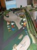
A new model airfield layout-More turf and the residents fly in !

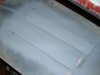
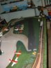
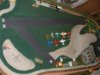
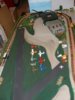
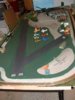
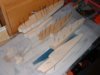
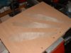
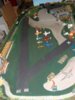
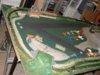
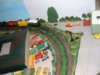
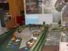
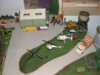
Today I did a lot more of the turf areas consuming quite a bit of flock in the process,after experimenting I found that the best way to handle this material is as follows 1/ Paint the area with brown umber acrylic artists paint,you do not have to use artists quality I used System 3 which is a students grade that is adequate and is cheaper because it uses more filler to pad it out,being tacky and of PVA formulae it is ideal,give a generous coat 2/ Sprinkle on the flock,I mixed the colours this time to good effect 3/ Next with the tip of a large brush stab gently vertically into the flock,this pounces it into the paint nicely 4/ Allow to dry overnight and the next day with a piece of paper and a dry brush simply brush off any surplus onto the paper and recycle placing into a jam jar or similar.

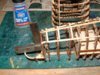
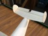
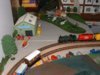
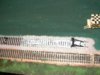
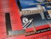
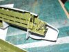
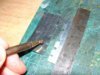
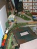
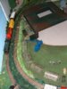
I have never done any ballasting of track so decided to give it a try,firstly I puddled PVA adhesive between the sleepers and outside of the track,then sprinkled ballast between the sleepers and at the sides,I realised straight away that I had added too much gravel and with a dental flat tool scraped off the surplus then checked the run with a spare bogie wheel,I am learning the art of railroading ! next time I will try a different way by first laying the ballast dry into the gaps of the sleepers then mix up some thinned PVA and flood the gravel.

I need to get this right as there is a lot of track to cover eventually.

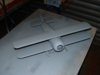
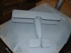
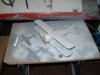
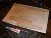
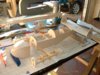
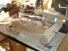
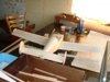
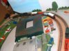
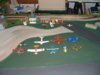
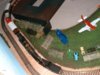
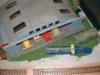
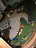
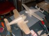
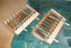
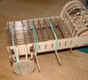
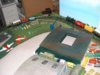
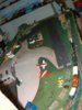
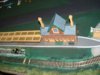
At the back of the layout I Adecided to add the industrial unit which also doubles up as the heliport including the air ambulance,the planned village will now be fabricated from the left to right of this on a removeable board as I need access to that particular area,I am planning something like some simple trestles positioned either end with the board butting up against the main layout,I will give that area some thought as I really would like to incorporate some rural houses of some type.

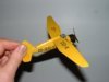
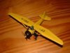
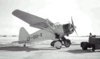
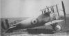
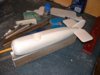
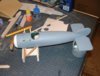
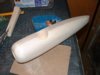
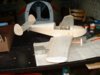
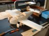
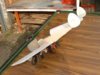
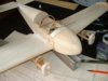
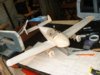
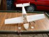
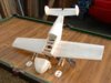
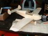
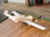
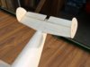
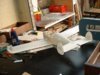
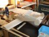
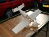
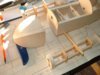
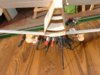
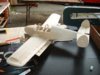
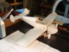
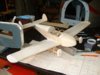
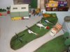
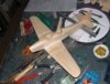
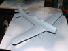
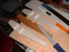
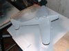
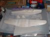
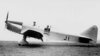
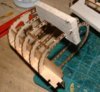
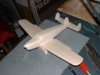
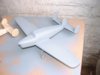
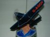
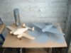
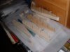
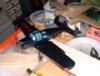
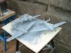
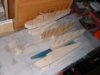
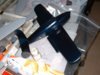
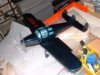
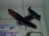
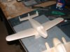
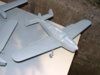
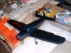
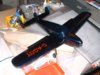
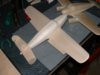
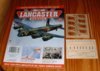
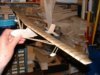
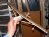
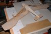
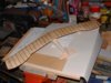
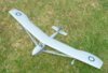
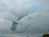
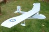
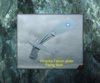
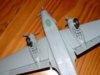
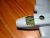
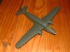
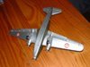
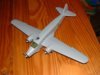
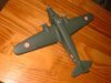
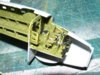
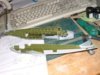
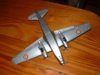
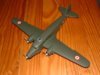
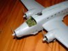
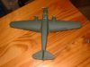
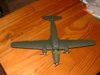
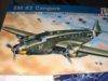
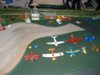
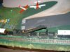
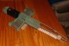
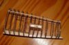
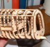
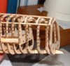
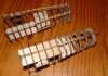
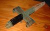
Meanwhile the aircraft have moved in ! a suitable selection of light aircraft and even a Wellington bomber as a cherished gate guard denoting the airfields past history as a bomber base.

Wonwinglo.

View attachment 28442

View attachment 28443

View attachment 28444

View attachment 28445

View attachment 28446

View attachment 28447

View attachment 28448

View attachment 28449

View attachment 28450

View attachment 28451

View attachment 28452

View attachment 28453

View attachment 140968

View attachment 140969

View attachment 140970

View attachment 140971

View attachment 140972

View attachment 140973

View attachment 140974

View attachment 140975

View attachment 140976

View attachment 140977

View attachment 140978

View attachment 140979
 

Attachments

  • AF#26.JPG
    AF#26.JPG
    3.1 KB · Views: 0
  • AF#20#.jpg
    AF#20#.jpg
    2.9 KB · Views: 0
  • AF#14.JPG
    AF#14.JPG
    2.9 KB · Views: 0
  • AF#21.JPG
    AF#21.JPG
    2.4 KB · Views: 0
  • AF#13.JPG
    AF#13.JPG
    3.2 KB · Views: 0
  • AF#7.JPG
    AF#7.JPG
    2.8 KB · Views: 0
  • AF#4.JPG
    AF#4.JPG
    2.5 KB · Views: 0
  • AF#24.JPG
    AF#24.JPG
    3.1 KB · Views: 0
  • AF#11#.jpg
    AF#11#.jpg
    2.8 KB · Views: 0
  • AF#6#.jpg
    AF#6#.jpg
    2.8 KB · Views: 0
  • AF#18.JPG
    AF#18.JPG
    2.9 KB · Views: 0
  • AF#19#.jpg
    AF#19#.jpg
    2.9 KB · Views: 0
Thread owner
Building the Partworks Avro Lancaster-Part 23 Rear fuselage mid upper turret section

Part 23 Consists of 8 formers,one keel piece,one floor piece and two side

stringers for the rear fuselage mid upper turret module.

This assembly differs from the previous ones in that the formers have a

slight lean to them which is prompted by the angle of the lower keel section

at the front,the lean follows the 8 formers through all the way.

Study the parts first and do a dry run to familiarise the assembly of them

in your mind,the lean of these parts made me realise that a simple jig would

aid assembly and rule out any differences in angles or alignment and make

for accuracy,for this I used a piece of balsa wood suitably cut to fit

between the formers with the correct angle sanded in at the lower end,it was

then a simple case of adding each former in turn and moving the spacer,the

picture will clarify how this was used.

Once the formers are glued they are still frail and unsupported at the top

prior to adding the two side stringers,once again a simple jig took the

guesswork out of holding them upright,all this consists of is a piece of

balsa wood with suitable slots filed into it at the exact width spacing

between them,this is just slid over the formers and held with a few weak

elastic bands,then the side stringers can be added with the bands tension

gently holding the stringers in place while they set,you will get the

general idea from the images here.

Eventually the mid upper turret shroud will sit between formers 104 & 105,it

will be interesting to see how this is tackled and what type of material the

shroud will be made from ?

Wonwinglo.

View attachment 28473

View attachment 28474

View attachment 28475

View attachment 28476

View attachment 28477

View attachment 28478

View attachment 140999

View attachment 141000

View attachment 141001

View attachment 141002

View attachment 141003

View attachment 141004
 

Attachments

  • new_PART 23 FORMER SPACER JIG.jpg
    new_PART 23 FORMER SPACER JIG.jpg
    2.5 KB · Views: 0
  • new_PART 23 JIG FOR KEEPING FORMERS IN LINE.jpg
    new_PART 23 JIG FOR KEEPING FORMERS IN LINE.jpg
    3.3 KB · Views: 0
  • new_PART 23 FORMER SPACER JIG END ON.jpg
    new_PART 23 FORMER SPACER JIG END ON.jpg
    3 KB · Views: 0
  • new_PART 23 ANGLE SPACER JIG FOR FORMERS.jpg
    new_PART 23 ANGLE SPACER JIG FOR FORMERS.jpg
    2.9 KB · Views: 0
  • new_PART 23 REAR TURRET SECTION ASSEMBLED.jpg
    new_PART 23 REAR TURRET SECTION ASSEMBLED.jpg
    3.2 KB · Views: 0
  • new_PART 23 COVER.jpg
    new_PART 23 COVER.jpg
    2.9 KB · Views: 0
Thread owner
Building the Parnall 382 training aeroplane

The final Parnall aircraft made by Parnall was a open two seat trainer derivative of the Heck to specification T.1/37 and called the Parnall 382 or the Heck 3. It featured the Heck's advanced wing and had a speed range of 139mph to 43mph, it made its first flight in 1939. At Marlesham Heath it was pleasant to fly assessed as generally good as a trainer and, with a number of modifications, was acceptable for service but sadly for Parnall no order was forthcoming. It was to be the last Parnall machine to fly, for after that Parnall turned to the vitally needed gun turrets of Archie Frazer-Nash's design which occupied the Yate factory throughout the war.

As a model subject it makes for a beautifully shaped aeroplane to add to any historical collection,the enclosed photographs show the construction from first cuts of the wood to get the correct shapes.

Wonwinglo.

View attachment 21564

View attachment 28479

View attachment 28480

View attachment 28481

View attachment 28482

View attachment 28483

View attachment 28484

View attachment 28485

View attachment 28486

View attachment 28487

View attachment 141005

View attachment 141006

View attachment 141007

View attachment 141008

View attachment 141009

View attachment 141010

View attachment 141011

View attachment 141012

View attachment 141013
 

Attachments

  • Parnall type 582 RS.jpg
    Parnall type 582 RS.jpg
    3.2 KB · Views: 0
  • PARNALL TYPE 582 PRIMER#.jpg
    PARNALL TYPE 582 PRIMER#.jpg
    2.3 KB · Views: 0
  • new_PARNALL 382 FUSE & WINGS.jpg
    new_PARNALL 382 FUSE & WINGS.jpg
    2.4 KB · Views: 0
  • new_PARNALL 382 FUSELAGE SIDES#1.jpg
    new_PARNALL 382 FUSELAGE SIDES#1.jpg
    2.7 KB · Views: 0
  • new_PARNALL 382 CLAMP UP THE FUSELAGE SIDES#1.jpg
    new_PARNALL 382 CLAMP UP THE FUSELAGE SIDES#1.jpg
    2.5 KB · Views: 0
  • PARNALL TYPE 582 PRIMER.jpg
    PARNALL TYPE 582 PRIMER.jpg
    2.2 KB · Views: 0
  • new_PARNALL 382 FUSE AND WINGS.jpg
    new_PARNALL 382 FUSE AND WINGS.jpg
    2.4 KB · Views: 0
  • PARNALL TYPE 582.jpg
    PARNALL TYPE 582.jpg
    3.2 KB · Views: 0
  • 382.jpg
    382.jpg
    1.3 KB · Views: 0
Thread owner
Building the Partworks Avro Lancaster-Part 24 Rear fuselage module crew access point

Part 24 includes wood fret to make the rear fuselage portion where the crew

access door is situated,this follows the same constructional techniques as

previous fuselage sections but there are a few areas that need careful

assembly and a few production errors need addressing and correcting to get

it to fit together properly,nothing serious just where the computer

technolgy has mis-aligned a few parts on the laser cutting template,as these

independant builds are done any items like this are highlighted to make

things easier for other builders.

The issue contains- 1 X Liteply fret,2 x Alignment stringers and a small

piece of brass rod for the entrance stanctions.

Method- Remove & fettle the wood parts as you need them,a chisel ended craft knife

blade has been found the most useful for this operation as you can press

downwards more directly,if any of the parts do not drop straight out then

turn the ply over and see where the problem lies,carefully run the blade a

few times to break the join,this should do the trick,if you see a line of

broken burns on the rear then this indicates a non perfect laser burn.

Observe the slight angle of former 103 in relation to the floor panel,do a

dry run first to observe the subtle slant of this former,apply adhesive and

press the part fully home onto part 115 and the lower keel member,allow to

dry properly.

Next make a simple balsawood angle jig for the other formers to correspond

with this master former and check each one in turn as you glue them into

place,this takes the guesswork out of the rigging of the formers and

certainly makes the job easier,keep going until you get to former 111 but DO

NOT glue former 110 in place at this stage as suggested in the magazine ,if

you do then this makes it difficult to deal with the entrance step which is

quite fiddly to get right.

Instead assemble parts 112a & 112b first,these are the crew door entrance

frame pieces that fit top and bottom,in order for the lower 112b to fit into

the centre half former a small error has crept in and you will need to take

a little off the slot to make it fit in line,I found this error corresponded

on both of my models so I am fairly certain that you will also encounter

it,use a warding file or similar to adjust the part to fit properly.

Once the above are fitted then it is time to fit the entry step itself,once

again it is not a good fit and needs a bit of rework to make it fit snugly

into place,mark the areas to be removed with a thin propelling pencil and

use the warding file to rectify it,at the same time slightly open up the

holes where the brass rods fit,now just press them into place and leave

plenty of extra length to them,do not cut to size as recommended in the

magazine,once you are happy with the fit of the wooden step piece glue it

into place and allow to dry out.

Next push the brass rods down flus with the floor and run thin cyno into the

holes in the wood step and a few dabs at the lower end and allow the

capillary action of the cyno to do its job,once cured cut the upper portion

of each rod off with flush edge side cutters ( obtainable from your model shop on

the tools stand,highly recommended for use with this model ) run over with

the file.

Now proceed to the last former No.110 and glue it into place,the reason for

leaving this until last is that it gets in the way of assembling that small

step.

Now slip the slotted former jig we made last time over the unsupported

formers and glue into place the wooden supporting side stringers,allow to

dry and cut off the ends of these finally sanding the ends of the formers

carefully with a sanding block.

As a small embellishment I added a small piece of thin card over the joins

on the step,this neatens it off nicely.

Do not attempt at this stage to sand the door frame pieces,this will be done

later when the area has been stringered and much stronger to handle.

This sounds a lot of work for this particular module but any care taken in

the individual assemblies at this stage especially as regards alignment will

pay off towards the final assembly,just to check things out I did a dummy

run shown here of the various fuselage modules that we have built so far,it

also serves to see how those slanted formers come into play in relation with

the other ones.

Taking a look at what detail is possible at the rear ie Cartridge shutes etc

for the guns in the mid upper and rear turret it may be better to leave some

of the stringers off until we know A/ what will be supplied with the

partworks and B/ What it is possible to fit ourselves ? we will have to see

at what stage Hachette say to seal them up as this could be an indication

that there is no more parts to add in that area,any pre-build like this

without knowing the full detail level set by the publishers is pioneering

work !

Wonwinglo.

View attachment 28552

View attachment 28553

View attachment 28554

View attachment 28555

View attachment 28556

View attachment 28557

View attachment 141078

View attachment 141079

View attachment 141080

View attachment 141081

View attachment 141082

View attachment 141083
 

Attachments

  • new_PART 24 GRIP FORMERS.jpg
    new_PART 24 GRIP FORMERS.jpg
    3.9 KB · Views: 0
  • new_new_PART 24 ADD STEP AND LOOSELY FIT BRASS RODS.jpg
    new_new_PART 24 ADD STEP AND LOOSELY FIT BRASS RODS.jpg
    4.2 KB · Views: 0
  • new_PART 24 USE THE SLOTTED JIG TO ALIGN THE FORMERS.jpg
    new_PART 24 USE THE SLOTTED JIG TO ALIGN THE FORMERS.jpg
    3.4 KB · Views: 0
  • new_PART 24 GRIP FORMERS NEAR CREW ENTRANCE.jpg
    new_PART 24 GRIP FORMERS NEAR CREW ENTRANCE.jpg
    3.8 KB · Views: 0
  • new_PART 24 COVER.jpg
    new_PART 24 COVER.jpg
    2.6 KB · Views: 0
  • new_PART 24 ADD STEP AND LOOSELY FIT BRASS RODS.jpg
    new_PART 24 ADD STEP AND LOOSELY FIT BRASS RODS.jpg
    4.2 KB · Views: 0
Thread owner
Building the Miles Messenger light aeroplane.

The Miles M-38 Messenger was a British light communications and air observation post aircraft of the second world war The Miles M-38 Messenger was a low-wing cantilever monoplane of one-piece all-wooden construction powered by a De Havilland Gipsy-Major ID 4-cylinder in-line inverted air cooled engine providing a top speed of 193 kmh. The Miles M-38 Messenger carried a crew of three or four and was adaptable for use as an air ambulance air-taxi and light freighter.

Wonwinglo.

The model follows my usual construction of a balsa/ply/balsa laminate,this gives exact centreline location and makes carving easier without any drifting from the plan view centreline shape,simple card templates are used for all parts both for cutting purposes and later on location of control surfaces etc,they form a constant guide throughout the build.

View attachment 28558

View attachment 28559

View attachment 28560

View attachment 28561

View attachment 28562

View attachment 28563

View attachment 28564

View attachment 28565

View attachment 28566

View attachment 28567

View attachment 28568

View attachment 28569

View attachment 28570

View attachment 28571

View attachment 28572

View attachment 28573

View attachment 28574

View attachment 28575

View attachment 28576

View attachment 28577

View attachment 141084

View attachment 141085

View attachment 141086

View attachment 141087

View attachment 141088

View attachment 141089

View attachment 141090

View attachment 141091

View attachment 141092

View attachment 141093

View attachment 141094

View attachment 141095

View attachment 141096

View attachment 141097

View attachment 141098

View attachment 141099

View attachment 141100

View attachment 141101

View attachment 141102

View attachment 141103
 

Attachments

  • MILES MESSENGER ASSEMBLED.jpg
    MILES MESSENGER ASSEMBLED.jpg
    2.6 KB · Views: 0
  • MESSEMGER IN PRIMER.jpg
    MESSEMGER IN PRIMER.jpg
    2.1 KB · Views: 0
  • MAKING THE FUSELAGES FOR THE MILES TYPES.jpg
    MAKING THE FUSELAGES FOR THE MILES TYPES.jpg
    2.4 KB · Views: 0
  • MESSEMGER COMPLETED#2.jpg
    MESSEMGER COMPLETED#2.jpg
    2.1 KB · Views: 0
  • MILES MESSENGER AND GMINI.jpg
    MILES MESSENGER AND GMINI.jpg
    3 KB · Views: 0
  • MESSEMGER AND GEMINI SPRAY.jpg
    MESSEMGER AND GEMINI SPRAY.jpg
    2.4 KB · Views: 0
  • GLUEING UP THE LAMINATED FUSELAGES FOR MILES TYPES.jpg
    GLUEING UP THE LAMINATED FUSELAGES FOR MILES TYPES.jpg
    2.3 KB · Views: 0
  • Miles messenger details added RS.jpg
    Miles messenger details added RS.jpg
    3.2 KB · Views: 0
  • GEMINI MESSENGER WHITNEY STRAIGHT IN PRIMER.jpg
    GEMINI MESSENGER WHITNEY STRAIGHT IN PRIMER.jpg
    2.8 KB · Views: 0
  • MESSENGER WHITNEY STRAIGHT FUSELAGE PIECES.jpg
    MESSENGER WHITNEY STRAIGHT FUSELAGE PIECES.jpg
    2.4 KB · Views: 0
  • MILES MESSENGER PAINTED BLUE.jpg
    MILES MESSENGER PAINTED BLUE.jpg
    3 KB · Views: 0
  • MILES MESSENGER COCKPIT ADDED.jpg
    MILES MESSENGER COCKPIT ADDED.jpg
    3.2 KB · Views: 0
  • MESSEMGER COMPLETED#3.jpg
    MESSEMGER COMPLETED#3.jpg
    2.1 KB · Views: 0
  • PLY INNERS WHITNEY STRAIGHT MESSENGER GEMINI SOLIDS.jpg
    PLY INNERS WHITNEY STRAIGHT MESSENGER GEMINI SOLIDS.jpg
    2.2 KB · Views: 0
  • MILES MESSENGER FRONT VIEW.jpg
    MILES MESSENGER FRONT VIEW.jpg
    2.7 KB · Views: 0
  • MILES MESSENGER.jpg
    MILES MESSENGER.jpg
    2.4 KB · Views: 0
  • MESSENGER WITH REGN TYPES.jpg
    MESSENGER WITH REGN TYPES.jpg
    3.2 KB · Views: 0
  • MILES MESSENGER DETAILS ADDED.jpg
    MILES MESSENGER DETAILS ADDED.jpg
    3.2 KB · Views: 0
  • MESSENGER WITH REGN.jpg
    MESSENGER WITH REGN.jpg
    3.2 KB · Views: 0
  • MILES MESSENGER ASSEMBLED WITH GEMINI.jpg
    MILES MESSENGER ASSEMBLED WITH GEMINI.jpg
    2.6 KB · Views: 0
Thread owner
Building the Partworks Avro Lancaster-Part 25 Wing Split Trailing edge section

Part 25 contains parts to build one out of two Split trailing Edge sections

for the wings,this is the area where the flap assembly is located.

The parts you get are- 2 Lite ply frets,one has 8 trailing edge ribs,the

other has two solid end ribs plus a leading spar and a rear top trailing

edge board,plus a strip of wood to make a locating spar.

Basic assembly is fairly straightforward but there is a better and more

accurate way to locate the ribs than is illustrated in the magazine,this is

the way that I tackled it which is straightforward -

1/ Firstly I added the two end solid ribs which must be fixed at 90

degrees,use a small metal set square to get these exact,or failing the

square you could use one of the wooden offcuts from the wood parts to use as

a square,allow these to dry out properly overnight.

2/ Instead of adding each of the 8 ribs in turn as suggested,I fixed each

one with PVA adhesive into the front spar slots all in one go,now leave the

parts to half set when you can gently move the ribs to line up with the

upper slotted board piece,do not apply glue to that at this stage but simply

add elastic bands to keep everything in place,allow to dry overnight.

3/ Next day release the bands remove the board and apply adhesive to the

slots, this way you will get all of the ribs lined up exactly and in the

right place without guesswork,make sure that the board sits flush with the

thin trailing parts of the ribs,use clothes pegs or similar to hold that

area in place as the adhesive sets.

4/ Now add the single wood spar supplied,allow to dry and sand the item up

with a sanding block.

Any issues ? Yes, once again the parts were difficult to remove from the

frets with the laser cutting not going right through as they should have

done,to remove the parts first cut through the conventional break lines as

normal,now turn the fret over and observe where they have not broken

through,use a craft knife to join up the dotted bits where the break is not

clean,take your time until they release,push out the small holes if blocked

with a pointed tool,sand any rough edges.

The above is more of an inconvenience than a major problem but do not

attempt to force out the fragile parts,they will break easily.

Comment: It would be much easier to assemble parts like this over a drawing

as is standard procedure with wooden kit building,it would take the

guesswork out of assembling things in your hand,partworks always seem

reluctant to include drawings ? but in spite of this we will continue to

find better ways of assembly than shown in the partworks.

Wonwinglo

View attachment 28704

View attachment 28705

View attachment 28706

View attachment 141230

View attachment 141231

View attachment 141232
 

Attachments

  • new_PART 25 WING TRAILING EDGE ASSEMBLED.jpg
    new_PART 25 WING TRAILING EDGE ASSEMBLED.jpg
    2.4 KB · Views: 0
  • new_PART 25 WING TRAILING EDGE FLAP AREA SET ANGLE.jpg
    new_PART 25 WING TRAILING EDGE FLAP AREA SET ANGLE.jpg
    3.2 KB · Views: 0
  • new_PART 25 COVER.jpg
    new_PART 25 COVER.jpg
    2.8 KB · Views: 0
Thread owner
Building the Slingsby Falcon Flying boat glider

This unique glider flying boat was tested after World War 2 from Lake Windermere,the concept was to provide flying training for ATC cadets where there was a lack of conventional airfields,the Falcon glider was towed aloft with a speed boat to altitude then released over the water landing area,the only problem encountered was tow rope drag on the water but this was eventually solved with the use of different materials and technique in getting the glider to plane on the water as any conventional flying boat does.

My model was built virtually from scrap materials from other projects,the ribbing effect on the wings was represented by laying button thread onto the balsa wings then covering with Modelspan tissue doped into place,the finish is Holts grey primer.

The model makes for an unusual historical subject and creates a talking point whenever people see it.

Wonwinglo.

View attachment 28707

View attachment 28708

View attachment 28709

View attachment 28710

View attachment 28711

View attachment 28712

View attachment 28713

View attachment 28714

View attachment 28715

View attachment 28716

View attachment 28717

View attachment 141233

View attachment 141234

View attachment 141235

View attachment 141236

View attachment 141237

View attachment 141238

View attachment 141239

View attachment 141240

View attachment 141241

View attachment 141242

View attachment 141243
 

Attachments

  • new_SLINGSBY FALCON HELD#1.jpg
    new_SLINGSBY FALCON HELD#1.jpg
    3.2 KB · Views: 0
  • new_SLINGSBY FALCON TOGETHER.jpg
    new_SLINGSBY FALCON TOGETHER.jpg
    2.9 KB · Views: 0
  • new_SLINGSBY FALCON TOGETHER.jpg
    new_SLINGSBY FALCON TOGETHER.jpg
    2.9 KB · Views: 0
  • new_SLINGSBY FALCON FRONT.jpg
    new_SLINGSBY FALCON FRONT.jpg
    3.1 KB · Views: 0
  • SLINGSBY FALCON UNDERSIDE.jpg
    SLINGSBY FALCON UNDERSIDE.jpg
    2.4 KB · Views: 0
  • SLINGSBY FALCON REAR VIEW.jpg
    SLINGSBY FALCON REAR VIEW.jpg
    2.9 KB · Views: 0
  • FALCON DEF#3 GR.jpg
    FALCON DEF#3 GR.jpg
    2.6 KB · Views: 0
  • FALCON DEF#1.jpg
    FALCON DEF#1.jpg
    1.6 KB · Views: 0
  • FALCON DEF#2 FR.jpg
    FALCON DEF#2 FR.jpg
    2.6 KB · Views: 0
  • FALCON DEF#4.JPG
    FALCON DEF#4.JPG
    2.5 KB · Views: 0
  • FALCON DEF FR TEXT.jpg
    FALCON DEF FR TEXT.jpg
    2.7 KB · Views: 0
What never fails to amaze me is the number of times you come up with an aircraft that I have never even heard of before. I take it a flying boat glider was designed to be towed up by a sea plane, which I have always thought required a lot of power anyway to get airbourne. Do you know if this aircraft ever flew?
 
Thread owner
No not towed by a seaplane Richard,it was towed aloft by a speed boat,the flying boat glider made many flights successfully from Windermere,there is a photograph of it in the steam museum at the lake.

Its an oddball but there have been other flying boat gliders built over the years some in Russia.
 
That must have been a bit of a hairy flight, I'd be worrying that the boat was going to turn in plenty of time to prevent me having to land in the trees!
 
Thread owner
Building the Italeri SM.82 Canguru.

This magnificant aeroplane needed the full justice that Italeri have put into this kit of the SM.82,having built scores of somewhat ill fitting Italeri kits in the past this one came as some surprise at its ease of assembly and has made up into a lovely model for the collection.

Due to the spell of cold damp weather I have been forced into the warm at home with my portable tool kit away from the workshop,thus a plastic model this time as opposed to my wooden scratch built models of late,I have plenty of models in the stash so lets get some of them built whilst the opportunity presents itself.

First inspection of the kit reveals the wealth of not only external detail but beautifully engraved interior right down to the bottom of the tail area,the stringers and formers are all there together with the spartan bench seats for the hardy paratroopers which do need care and patience to get fitted properly,the cockpit is nicely detailed as can be seen in the pictures with a well fitting canopy.

Once the interior has been painted then the sides can be dry fitted to ensure that the upper and lower floor levels ala Airbus 380 fit nice and snug,it seems such a pity to hide all of that lovely detail but my thought on this is that at least you know it is there and not an hollow void in your mind,how many times have you super detailed a kit internally only to find that once everything is closed up you cannot see a thing ? each to his or her own but in this case I enjoyed fitting it out even if afterwards it cannot be seen.

The option for dropping the fowler flaps was just too great to resist and has made for a most attractive sitting model both on the ground and if I suspend it as many of my models are,the tiny flap brackets are provided for both the up or down flap positions,the propellers have some good decals both fore and aft which look most effctive on the silver blades.

The wing join did need a thin run of Squadron putty on the lower but nothing too drastic to get the dihedral correct,remember that dihedral is important to give the aeroplane its correct scale sit,get it wrong and every time you look at it then it annoys you.

Take care with the undercarriage and build that in stages allowing the intricate struts to cure before proceeding to the next stage,the computer heat comes in handy to assist drying,just sit your model parts onto your tower and allow the gentle heat to rise and do the drying in between sequences of building,works every time.

Final assembly brings you a rugged model except for those pesky wingtip mounted pitot tubes which soon got discarded as they got knocked off whilst handling.

I normally use Halfords white primer my models before painting but once again due to the weather as I do my rattle can work outside with this one simply washed it down and got on with the painting,I use the excellent fine pigments of Warhammer paints which flow beautifully,cannot be bothered with airbrushes personally as they take too much time to clean and as yet I have not found a model that suits me or will handle acrylics well ? I just use the very best expensive artists quality brushes and flow on the paint,making sure that any paint left is washed out with soap and water for next time round,the end results can be seen and once again sitting the model onto the computer drys out the paint well.

Decals were for some Luftwaffe examples plus the Italian example that I chose,when dry then I will overpaint the white areas by hand to get rid of the translucant paint,a protective coat of Johnsons will then seal in the markings.

Overall a very pleasant model kit to build up and the subject matter for me at least is just what I needed,well done Italeri.

Wonwinglo.

View attachment 28884

View attachment 28885

View attachment 28886

View attachment 28887

View attachment 28888

View attachment 28889

View attachment 28890

View attachment 28891

View attachment 28892

View attachment 28893

View attachment 28894

View attachment 28895

View attachment 28896

View attachment 28897

View attachment 28898

View attachment 28899

View attachment 28900

View attachment 28901

View attachment 141410

View attachment 141411

View attachment 141412

View attachment 141413

View attachment 141414

View attachment 141415

View attachment 141416

View attachment 141417

View attachment 141418

View attachment 141419

View attachment 141420

View attachment 141421

View attachment 141422

View attachment 141423

View attachment 141424

View attachment 141425

View attachment 141426

View attachment 141427
 

Attachments

  • SM82 INTERIOR#1.JPG
    SM82 INTERIOR#1.JPG
    2.7 KB · Views: 0
  • SM82 LOWER#10.JPG
    SM82 LOWER#10.JPG
    2.6 KB · Views: 0
  • SM82 WINGS ON#5.JPG
    SM82 WINGS ON#5.JPG
    2.5 KB · Views: 0
  • SM82 COCKPIT#6.JPG
    SM82 COCKPIT#6.JPG
    2.3 KB · Views: 0
  • SM82 PAINTED#11.JPG
    SM82 PAINTED#11.JPG
    2.4 KB · Views: 0
  • SM82 LOWER DECAL#17.JPG
    SM82 LOWER DECAL#17.JPG
    2.6 KB · Views: 0
  • SM82 ASSEMBLED#8.JPG
    SM82 ASSEMBLED#8.JPG
    2.6 KB · Views: 0
  • SM82 DECALLED#16.JPG
    SM82 DECALLED#16.JPG
    2.5 KB · Views: 0
  • SM82 INTERIOR#4.JPG
    SM82 INTERIOR#4.JPG
    3.4 KB · Views: 0
  • SM82 INTERIOR#2.JPG
    SM82 INTERIOR#2.JPG
    2.9 KB · Views: 0
  • SM82 DECAL#18.JPG
    SM82 DECAL#18.JPG
    2.5 KB · Views: 0
  • SM82 DECALLED#15.JPG
    SM82 DECALLED#15.JPG
    2.5 KB · Views: 0
  • SM82 ASSEMBLED#9.JPG
    SM82 ASSEMBLED#9.JPG
    2.7 KB · Views: 0
  • SM82 PAINTED#13.JPG
    SM82 PAINTED#13.JPG
    2.4 KB · Views: 0
  • SM82 PAINTED#12.JPG
    SM82 PAINTED#12.JPG
    2.5 KB · Views: 0
  • SM82 PROPELLERS#7.JPG
    SM82 PROPELLERS#7.JPG
    2.4 KB · Views: 0
  • SM82 INTERIOR#3.JPG
    SM82 INTERIOR#3.JPG
    3.3 KB · Views: 0
  • SM82 BOX#19.JPG
    SM82 BOX#19.JPG
    3.1 KB · Views: 0
Thread owner
Building the Partworks Avro Lancaster-Part 26 lets complete the split flap

Part 26 contains details of completing the split flap assembly that we dealt

with last week,plus the first pieces of aluminium as yet for the model in

this case for the floor panels in the centre section fuselage,I wonder if

this is going to be the same gauge metal as used to clad the model

eventually ? we will have to see,I am curious also to see how the curved

metal sections will be dealt with as there are plenty of them ?

List of parts this week-A bit tardy really,a bundle of stringers to use on

the split flap assembly,plus two pre-shaped thin alloy panels which are for

the cente section fuselage area,despite this there is plenty of work to do

with these items as you will see here.

The stringers are straight and useable,you get a generous amount as well.

Assembly-Make a start by sanding the trailing edge of the split flap

assembly,you only need to make a small chamfer so that the flaps will sit

flush inside the trailing edge,next commence to add the stringers top and

bottom of this assembly but before you do mix up some PVA glue 50/50 with

water and paint it into the slots for the stringers and allow to dry before

fixing them into place with thin cyno,a really easy way to hold the

stringers is as shown in the photograph here,take two toothpicks or similar

and bring a few elastic bands over the assembly to the other side,do this in

three places to gently hold the stringers in place while they dry,I add them

dry and then take the part outside and flood the joints with thin Cyno,the

adhesive creeps right underneath the stringers and locks them solid,once

cured sand the ends flush and also sand the stringers gently all over with

your sanding block,this gets rid of any bumps or stray adhesive.

The magazine suggests cutting and placing stringers 'between' the trailing

edge of the ribs,this does not work very well but I could not do much about

it on this section and had to do them individually,however next time on the

ones on the other side I will add the stringers 'before' the rear board is

glued into place at Part 25,the stringers will then be added then cut outs

added where the ribs go in between rather than the other way round which is

poor practise and very fiddly,the way they do it makes hard work of a simple

task,so for anyone wanting to incorporate this remember to do it at stage

25,ie last weeks build.

Floor panels-These will need careful cutting and trimming to make them fit

between the formers in the floor area,use a pair of nail scissors to open

out the slots in the thin aluminium,then a craft knife to do the other

opposite cuts,make sure that they both fit snugly and do a dry run first

before adding adhesive,but first they need to be represented to have rows of

rivets fore and aft,to do this select a suitable watch gear wheel and fit it

into the end of an old paintbrush or piece of dowel,add a spindle from a

nail or piece of wire and peen the end over so that the watch wheel runs

smoothly,now trap the plates between a metal ruler and carefully run the

wheel along the aluminium to make rows of rivets,you soon get the hang of

it,as you do this the aluminium will start to curl upwards,to rectify this

take a piece of old broom handle and gently roll the metal plates back and

front with the dowel onto a piece of carpet underlay,it will soon straighten

out,see the photograph to get the idea.

Once the floorplates are ready,turn them over and roughen up the metal with

some wet and dry paper to give a key for the adhesive,I used UHU clear

rather than cyno as suggested to stick them in place as this can be moved

around a bit before it sets,you only need a small amount of adhesive as this

is not a structural area just an embellishment,get the parts ready on your

bench knowing where they fit and apply the adhesive with a cocktail stick

and work quickly before it starts to string.

As yet I have not painted mine as I want to to treat them with white vinigar

first applied with a brush to etch them before adding any colour,they do

look effective as can be seen in the picture,the vinigar will give a key to

the paint as it bites into the surface slightly then washed off with water

to neautralise the metal.

I painted the flap area underneath with acrylic black paint done with a

brush.

View attachment 29032

View attachment 29033

View attachment 29034

View attachment 29035

View attachment 29036

View attachment 29037

View attachment 29038

View attachment 141558

View attachment 141559

View attachment 141560

View attachment 141561

View attachment 141562

View attachment 141563

View attachment 141564
 

Attachments

  • new_PART 26 FLAPS BEING STRINGERED.jpg
    new_PART 26 FLAPS BEING STRINGERED.jpg
    3.1 KB · Views: 0
  • new_SIMPLE STICK METHOD OF HOLDING STRINGERS#2.jpg
    new_SIMPLE STICK METHOD OF HOLDING STRINGERS#2.jpg
    3.3 KB · Views: 0
  • new_PART 26 COVER.jpg
    new_PART 26 COVER.jpg
    3.2 KB · Views: 0
  • new_PART 26 MARKING RIVETS ON FLOOR PANELS#2.jpg
    new_PART 26 MARKING RIVETS ON FLOOR PANELS#2.jpg
    2.8 KB · Views: 0
  • new_SIMPLE STICK METHOD OF HOLDING STRINGERS.jpg
    new_SIMPLE STICK METHOD OF HOLDING STRINGERS.jpg
    2.8 KB · Views: 0
  • new_PART 26 ADDING FLOOR PANELS TO CENTRE SECTION#2.jpg
    new_PART 26 ADDING FLOOR PANELS TO CENTRE SECTION#2.jpg
    3.4 KB · Views: 0
  • new_PART 26 ROLLING ALLOY FLOOR PANELS AFTER RIVETTING#2.jpg
    new_PART 26 ROLLING ALLOY FLOOR PANELS AFTER RIVETTING#2.jpg
    2.6 KB · Views: 0
Thread owner
More work on the model airfield and railway layout.

Since my last diary on the model airfield layout and allied railway system I have added lots of scenic work to the layout,out came the bags of coloured flock in various shades and plenty of old acrylic paint that had seen better days sitting around in my studio put to good use,the bits that had formed did not matter as I sprinkled the flock dust onto the wet paint,I soon found out that a stabbing action with a dry bristle brush gave a variety of shades and finishes,for anyone who has not yet tackled scenery whether it be for a diorama of something larger then go for it,you will find the experience of adding fields and roads plus those essential runways a really relaxing experience,the good thing is that if you do not like the effect when dry you can soon go over it again,the build up of colour looks even more effective as well.

Experiments with the track ballast have been interesting, and now I have found an excellent liquid product made by a company called 'Woodland Scenics' it is far better than PVA adhesive for adding the ballast and can be lightly sprayed over with a garden spray to lock the stones in place,working a foot at a time that part is coming along.

A trip to the friendly local train shop found some bargain buildings that the owner had brought in second hand,a neat water tower and a decent sized station have been added,if something that I see looks suitable and is reasonably priced then it is added.

The next big task is to make a goods yard on a removeable panel alongside the main board,this will be used for shunting with the possibility later of adding a fiddle yard to the layout,a village is still planned as well if I can fit this in,but there is always room for improvement and scenes can be changed and upgraded as necessary or if the fancy takes me.

All electrical connections on the main track have been soldered permanently for reliability of operation,it was quickly found the things that can go wrong simply connecting rail together,especially where points are involved,keeping the gaps between rails tight is essential for care free operation,yes I am learning fast in this new area for me !

The photographs show the steady progress,some things will be moved and others added in due course.

Wonwinglo.

View attachment 29039

View attachment 29040

View attachment 29041

View attachment 29042

View attachment 29043

View attachment 29044

View attachment 29045

View attachment 29046

View attachment 29047

View attachment 29048

View attachment 29049

View attachment 29050

View attachment 29051

View attachment 29052

View attachment 141565

View attachment 141566

View attachment 141567

View attachment 141568

View attachment 141569

View attachment 141570

View attachment 141571

View attachment 141572

View attachment 141573

View attachment 141574

View attachment 141575

View attachment 141576

View attachment 141577

View attachment 141578
 

Attachments

  • 20101124_13.JPG
    20101124_13.JPG
    3 KB · Views: 0
  • 20101124_4#.jpg
    20101124_4#.jpg
    2.9 KB · Views: 0
  • 20101124_3#.jpg
    20101124_3#.jpg
    2.9 KB · Views: 0
  • 20101124_6#.jpg
    20101124_6#.jpg
    3.1 KB · Views: 0
  • 20101124_8.JPG
    20101124_8.JPG
    2.7 KB · Views: 0
  • 20101124_10.JPG
    20101124_10.JPG
    2.9 KB · Views: 0
  • 20101124_5#.jpg
    20101124_5#.jpg
    2.9 KB · Views: 0
  • 20101124_7#.jpg
    20101124_7#.jpg
    3.1 KB · Views: 0
  • 20101124_2.JPG
    20101124_2.JPG
    3.2 KB · Views: 0
  • 20101124_12.JPG
    20101124_12.JPG
    2.9 KB · Views: 0
  • 20101124_1.JPG
    20101124_1.JPG
    3.1 KB · Views: 0
  • 20101124_14.JPG
    20101124_14.JPG
    2.6 KB · Views: 0
  • 20101124_11.JPG
    20101124_11.JPG
    2.9 KB · Views: 0
  • 20101124_9.JPG
    20101124_9.JPG
    2.7 KB · Views: 0
Thread owner
Build the Lancaster Bomber Partworks-Part 27 Rear fuselage section work around

Part 27 has the parts for the very rearmost fuselage section,this consists

of 5x whole formers,4x sub formers,2x panels that make a box to fit the

tailplane referred to as boards,a lower keel,plus two locating longerons.

Big issues.

What appears to be a straightforward assembly operation is certainly not

so,very few of the parts fit correctly due to being out of alignment and

once assembled the fuselage slopes down incorrectly from the top down

towards the tail giving a very odd look to this section of the fuselage,to

see what it looks like once assembled view the picture of all the fuselage

sections placed together,I have also included a rear fuselage section

drawing of the actual Lancaster to see how it should be,there is very little

if any slope towards the rear.

Regardless of this here is a sequence of what is wrong with this weeks parts

notwithstanding the innacuracy mentioned above ,I have built up the section

as they suggested ,this rear piece is incorrect and will not be used in my

model as it is,my initial plan is to re-draw out the particular area and

make a new section altogether from scratch a task that will be beyond many I

appreciate,however do not dispair as there may be a way to rebuild this area

from the existing parts and to rectify the error,either way there will be a

work around,what has happened is that the parts for this area have been

badly designed and do not fit the quality of the previous sections of the

model,almost as if two different people have been involved ? this is a major

obstacle and I wonder if the publishers are aware of the problem,you never

know with situations like this with these partworks ?

To fully explain the problem lets start at the point after the tailplane box

has been built up from parts 115a and 115b,part 117a a former sits up too

high up on the box which then puts the two side alignment stringer

positions out of line,the lower part of this former has to be trimmed to

bring it into alignment so it sits lower,it is best to leave this former

until all the others are in place then to trim the lower by dry fitting the

side stringers,next former 118 does not fit onto the end notches of the box

and needs to be opened out from the top where it mates with the said box,all

subsequent formers are too tight a fit onto the lower keel and need to be

opened up with a Swiss file in order to sit flush with the lower half of the

lower keel.

At what stage something needs to be finally addressed is dependant on when

this portion is joined up to the other fuselage sections so I have placed

this situation on hold for the time being until more is known about the

surrounding areas such as the tailplane fixing.

Part 27 discussed in detail above is now sorted and a work around has

been devised to get the shape correct,this utilises all existing parts and

can easily be achieved by inexperienced model builders as it entails nothing

complicated,and once more all that is needed is a piece of strip wood 5

5/8th long plus some scrap ply which comes with the frets,I enclose a step

by step sequence to follow below-

1/ The Cause-The slope of the rear fuselage is the problem area,study shows that

the formers are the incorrect height causing a bowed gradual downwards

effect which is incorrect,assemble the parts as per instructions first.

2/ The Brief-Now cut a strip of 3/32 nd stripwood to 5 5/8th length,we will add this

as an extra stringer to get the rear fuselage as it should be.

3/ With a Warding file or similar carefully open out the topmost stringer

slots in the formers to accept the stripwood,keep checking to make sure that

it sits into all of the slots except the last three formers towards the rear

of the fuselage section,hold this in place for the time being with an

elastic band.

4/ Now with some scrapwood and a pencil mark out a new small upper mini

former that will sit just at the front of the rearmost original fomer ie the

last one,cut this out with a craft knife and sand smooth,now make a slot

with the file so that the stringer we have made sits snugly into each

former,make sure that the stringer is not pulled down as it should be level

all the way along,that is your guide.

5/ Now make two more mini upper former pieces in a similar fashion cutting a

slot and making sure they fit snug at the sides of the original formers that

were too short ( refer to the illustrations here to get the idea )

6/ Glue the new home made mini formers into place and when dry add the new

upper stringer,what a transformation ! the top line is as it should be with

a little bit of extra work,nothing should hinder any further work,all we

have done is to build up the formers a little and add the extra stringer to

bring everything into alignment.

Study the pictures,as they say a picture paints a thousand words.

Wonwinglo.

View attachment 29215

View attachment 29216

View attachment 29217

View attachment 29218

View attachment 29219

View attachment 29220

View attachment 29221

View attachment 141741

View attachment 141742

View attachment 141743

View attachment 141744

View attachment 141745

View attachment 141746

View attachment 141747
 

Attachments

  • new_PART 27 REAR FUSELAGE MOCK UP.jpg
    new_PART 27 REAR FUSELAGE MOCK UP.jpg
    2.2 KB · Views: 0
  • new_PART 27 REAR FUSELAGE SECTION SIDE.jpg
    new_PART 27 REAR FUSELAGE SECTION SIDE.jpg
    2.5 KB · Views: 0
  • new_PART 27 WORK AROUND#3.jpg
    new_PART 27 WORK AROUND#3.jpg
    4 KB · Views: 0
  • new_PART 27 WORK AROUND#2.jpg
    new_PART 27 WORK AROUND#2.jpg
    3.7 KB · Views: 0
  • new_PART 27 REAR FUSELAGE SECTION#2.jpg
    new_PART 27 REAR FUSELAGE SECTION#2.jpg
    2.9 KB · Views: 0
  • new_PART 27 REAR FUSELAGE SECTION MOCKED UP.jpg
    new_PART 27 REAR FUSELAGE SECTION MOCKED UP.jpg
    2.1 KB · Views: 0
  • new_PART 27 COVER.jpg
    new_PART 27 COVER.jpg
    2.7 KB · Views: 0
Thread owner
Building the Partworks Lancaster Bomber-Part 28 Tail gunners position

Part 28 contains parts to build the rear gunners turret base section,plus

the base portion for the mid upper gun turret.

The parts inventory is-

I X Ply fret of parts,3x strips of wood,2x small aluminium squares,plus a

pack of plastic stringers for Part 29.

Please note:Do not proceed with Part 28 until the important issues with the

rear fuselage upper contour have been completed,these were detailed last

week in a separate set of independant instructions as a work-around that

utilised the existing parts but added small portions of former to rectify

the issue.

Issues with Part 28- Various adjustments will need to be made in order for

all of the parts to fit snugly into place,these mostly apply to slots that

need opening out or some trimming to take place,as it is inevitable with any

wooden model subtle differences will occur model to model,below is a

reference to the items encountered-

1/ Part 128 will need careful adjustment in order to lie at exactly 90

degress to the rearmost former in order that the rear turret transparency

will fit level,as supplied it rides high at the lower half when Part 127 is

fitted throwing it out of alignment,dry check to see if any removal of wood

is needed at the lower longeron notch,see illustration.

2/ Part 130 elevator joiner plate needs careful alignment,once again some

removal of wood is needed at the upper slot of former 118 to make sure that

it sits level.

3/ The ramp section is too short and will only reach one slot,I fixed this

by adding a small piece of wood at the lower of part 115a in order that the

ramp will sit properly,fill the redundant slots either side of the ramp with

scrap wood.

4/ When the mid upper turret base section is completed do a through test fit

into the upper portion of the respective formers,you will find that the

slots will need some attention with a Swiss file in order for this section

to sit flush and level,check also for careful fore and aft alignment in

relation to the formers,adjust the slots as necessary before any glue is

applied,handle carefully as the half formers are very frail before this

section is added.

No matter how careful we have been with vertical former alignment and

spacing and utilisation of simple jigs small errors can and do creep in.

Thats about it for this week,remember the old adage 'Check twice,glue once'

View attachment 29341

View attachment 29342

View attachment 29343

View attachment 29344

View attachment 141867

View attachment 141868

View attachment 141869

View attachment 141870
 

Attachments

  • new_PART 28 COVER.jpg
    new_PART 28 COVER.jpg
    3.1 KB · Views: 0
  • new_PART 28 MAKE UP THE MID UPPER TURRET SURROUND.jpg
    new_PART 28 MAKE UP THE MID UPPER TURRET SURROUND.jpg
    3 KB · Views: 0
  • new_PART 28 MID UPPER TURRET BASE#.jpg
    new_PART 28 MID UPPER TURRET BASE#.jpg
    3.6 KB · Views: 0
  • new_PART 28 SQUARE UP THE TAIL GUNNERS POSITION#.jpg
    new_PART 28 SQUARE UP THE TAIL GUNNERS POSITION#.jpg
    3.6 KB · Views: 0
I had never realised just how detailed this model actualy is. The internal ribs and frames I'm sure will end up looking very realistic when painted up. Thanks for taking the time to show us this Barry, it is a very interesting model.
 
Thread owner
The Westland Lysander as a crop spraying agricultural aircraft in Canada

Imagine seeing one of these flying low over the crops ? well the subject has intrigued me for some years and a I decided to convert a standard Airfix Lizzy into one of these historic machines.

After WW2 surplus Canadian Lysander's could be purchased cheaply,most were sold off as scrap but six aircraft became crop sprayers with Westland Dusting services later selling them to Westland Spraying services at High River,Alberta.

The aircraft used the original fuel tanks for the pesticides and had special 45 gallon fuel tanks fitted just aft of the pilots seat,as you can see from the pictures this area including the aft fuselage fabric were metal clad.

The aircraft were in service from 1948 until as late as 1955 and known registrations are CF-DGI,CF-DRL,CF-FOA,CF-GFI note the application of the 'X' in the photograph.


The colours turned out to be yellow as thought,the scheme looks very good on the Lysander duster as flown in 1948 to 1950 from Alberta.

Note the fixed inboard leading edge slats,blanked off rear cockpit where the new fuel tank was fitted,the conventional fuel tanks were pressed into service for the pyrethan chemicals,the 'X' experimental category registration was probably because of the extensive modifications as a sprayer/duster,the normally fabric area aft of the fuselage has been replaced with metal panels which look as though they have Dzus fasteners for easy removal,this makes good sense as the pyrethan was highly corrosive and can run down the longerons and needed constant attention with a water blast after spraying operations.

The depletion of the outer leading slats is interesting,perhaps they were just not required for the low down operations that dusting and spraying demands ? there is very little on these aircraft and I would like to know more about the modifications to the airframe,one thing is for sure and that is the old Lizzie would have proved a robust and practical machine for this type of work,8 years of hard service is quite a lot for any agricultural aircraft.

For the conversion a standard Airfix Lysander kit was taken from the stash and turned into something re-creating a bit of history,it makes into an attractive and different subject and will join my other Lysander's and variants.

Basically the aft fuselage is smoothed off and a thin piece of plastikard in added on the sides to represent the metal cladding over the fabric areas that acted as inspection panels and making the fuselage capable of being easily hosed down during spraying operations,the rear cockpit is smoothed down as this too serves another purpose,that of the actual 45 gallon fuel tank in lieu of the real tank used as the hopper,the upper frame lines are retained and just painted over as per the real aircraft when used for spraying.

The fixed inboard slats are made from sprue filed on the rear and tiny supports made from plastic glued into place at the edges,the outboard slats were immobilised as they were no longer required for this task,the modifications required the experimental 'X' category makings but it is not known if these were retained after the initial test flying ?

View attachment 29881

View attachment 29882

View attachment 29883

View attachment 29884

View attachment 29885

View attachment 142407

View attachment 142408

View attachment 142409

View attachment 142410

View attachment 142411

View attachment 142907

View attachment 142908

View attachment 142909

View attachment 142910

View attachment 142911
 

Attachments

  • 20101224_8.jpg
    20101224_8.jpg
    1.9 KB · Views: 0
  • 20101224_2.jpg
    20101224_2.jpg
    2.4 KB · Views: 0
  • Lizzycropsprayer.jpg
    Lizzycropsprayer.jpg
    1.9 KB · Views: 0
  • LIZZY#10.JPG
    LIZZY#10.JPG
    1.8 KB · Views: 0
  • CROP SPRAYING LYSANDERS.JPG
    CROP SPRAYING LYSANDERS.JPG
    1.2 KB · Views: 0
  • Lizzycropsprayer.jpg
    Lizzycropsprayer.jpg
    1.9 KB · Views: 0
  • 20101224_2.jpg
    20101224_2.jpg
    2.4 KB · Views: 0
  • 20101224_8.jpg
    20101224_8.jpg
    1.9 KB · Views: 0
  • LIZZY#10.JPG
    LIZZY#10.JPG
    1.8 KB · Views: 0
  • CROP SPRAYING LYSANDERS.JPG
    CROP SPRAYING LYSANDERS.JPG
    1.2 KB · Views: 0
Thread owner
Spitfire schemes 1941 to 1942

SOME SPITFIRE SCHEMES 1941-1942.


Spitfire of American Eagle squadron based in the UK 1941-42.


Spitfire in British day fighter colourscheme 1942.

In the Autumn of 1941 the dark green and dark earth camouflage colours were abandoned on all day fighters operating in Great Britain in favour of dark green and dark sea grey or sea grey medium,The colour on the undersides was also changed and from that time onwards fighters were painted in sea grey medium which was a pale grey colour.A completely new marking introduced in September,1941 was a yellow stripe 6 inches wide along the leading edge of the wings,this commenced half way along the span and finished at the tips.


SPITFIRE


Thread owner
Building a scratch built Vickers ES1 Bullet

I first built this model some 58 ears ago ! so time to do a retake with modern adhesives and decent tools at my disposal,the Vickers ES1 was designed by Frank Barnwell,only a prototype of the ES1 was built,a few versions shown here saw their way to Belgium,the aircraft proved unpopular for its nasty behaviour of having small fires in the nose cowl where petrol collected.

Despite this it was certainly a very advanced machine for its day with its circular fuselage,there is also a passing resemblence to the Spad series if you look carefully.

All balsa wood with fittings made from scrap,propeeler was carved from a cigar box wood which must have been as old as the original design.

Plan comes from a 1930 issue of 'Air Stories' pulp magazine,super plans for their day draughted by the late James Hay Stevens.

Wonwinglo.

View attachment 31422

View attachment 31423

View attachment 31424

View attachment 31425

View attachment 31426

View attachment 31427

View attachment 31428

View attachment 31429

View attachment 31430

View attachment 31431

View attachment 31432

View attachment 31433

View attachment 31434

View attachment 31435

View attachment 31436

View attachment 31437

View attachment 31438

View attachment 31439

View attachment 31440

View attachment 31441

View attachment 31442

View attachment 144448

View attachment 144449

View attachment 144450

View attachment 144451

View attachment 144452

View attachment 144453

View attachment 144454

View attachment 144455

View attachment 144456

View attachment 144457

View attachment 144458

View attachment 144459

View attachment 144460

View attachment 144461

View attachment 144462

View attachment 144463

View attachment 144464

View attachment 144465

View attachment 144466

View attachment 144467

View attachment 144468
 

Attachments

  • ES1#A.jpg
    ES1#A.jpg
    2 KB · Views: 0
  • VICKERS ES1 BULLET.jpg
    VICKERS ES1 BULLET.jpg
    1.8 KB · Views: 0
  • ES1 BLOCK MARKED UP#2.jpg
    ES1 BLOCK MARKED UP#2.jpg
    2.4 KB · Views: 0
  • Vickers_E_S_1_rear_quarter_view.jpg
    Vickers_E_S_1_rear_quarter_view.jpg
    1.7 KB · Views: 0
  • ES1#F.jpg
    ES1#F.jpg
    2.3 KB · Views: 0
  • ES1 COCKPIT CARVED OUT.jpg
    ES1 COCKPIT CARVED OUT.jpg
    2.2 KB · Views: 0
  • BULLET FUSE BLANKS#4.jpg
    BULLET FUSE BLANKS#4.jpg
    1.9 KB · Views: 0
  • CLAMP UP THE BLANKS#1.jpg
    CLAMP UP THE BLANKS#1.jpg
    3.4 KB · Views: 0
  • ES1 WINGS#6.jpg
    ES1 WINGS#6.jpg
    2 KB · Views: 0
  • ES1 A FIRST COAT ON THE FUSELAGE.jpg
    ES1 A FIRST COAT ON THE FUSELAGE.jpg
    2.5 KB · Views: 0
  • 800px-Vickers_E_S_1.jpg
    800px-Vickers_E_S_1.jpg
    1.5 KB · Views: 0
  • ES1 WINGS#1.jpg
    ES1 WINGS#1.jpg
    3.1 KB · Views: 0
  • ES1#D.jpg
    ES1#D.jpg
    1.9 KB · Views: 0
  • Vickers_E_S_1_from_left.jpg
    Vickers_E_S_1_from_left.jpg
    1.7 KB · Views: 0
  • ES1 WINGS#2.jpg
    ES1 WINGS#2.jpg
    2.6 KB · Views: 0
  • ES1#I.jpg
    ES1#I.jpg
    2.5 KB · Views: 0
  • BULLET FUSE BLANKS#1.jpg
    BULLET FUSE BLANKS#1.jpg
    2.4 KB · Views: 0
  • ES1 TAIL MADE UP AND MOUNTED.jpg
    ES1 TAIL MADE UP AND MOUNTED.jpg
    2.7 KB · Views: 0
  • ES1 JIG.jpg
    ES1 JIG.jpg
    2.8 KB · Views: 0
  • A NICE ES1 ROUND FUSELAGE.jpg
    A NICE ES1 ROUND FUSELAGE.jpg
    2.4 KB · Views: 0
  • ES1 WINGS#3.jpg
    ES1 WINGS#3.jpg
    1.8 KB · Views: 0
Thread owner
Miles Gemini control line vintage model

This model has been on my mind for years when I purchased the plan a 1950's 'Model Aircraft' magazine drawing,it is a really super subject and the model went together well despite the age of that plan as it had faded a bit due to the dieline printing technique which is fugitive and you end up pencilling in the outlines to save the drawing itself.

I started by making up a set of parts like a kit,these took me several days to cut out working four hours a day in between drinking numerous cups of my favourite red bush tea !

Here you can see the progress so far having achieved the sheeting stage,all I need now are two vintage Elfin diesels or similar to bolt into place and fly her,this is the first control line model that I have built in 40 yearsand making that paxolin bellcrank brought back many memories,this is low tech modelling but what fun I have had in creating it,it has taken me back to my youth when I handled my very first model engine an ED Comp Special and a Keil Kraft Phantom control line trainer.

Wonwinglo

View attachment 35410

View attachment 35411

View attachment 35412

View attachment 35413

View attachment 35414

View attachment 35415

View attachment 35416

View attachment 35417

View attachment 35418

View attachment 35419

View attachment 35420

View attachment 35421

View attachment 35422

View attachment 35423

View attachment 35424

View attachment 35425

View attachment 35426

View attachment 35427

View attachment 35428

View attachment 35429

View attachment 35430

View attachment 35431

View attachment 35432

View attachment 35433

View attachment 148436

View attachment 148437

View attachment 148438

View attachment 148439

View attachment 148440

View attachment 148441

View attachment 148442

View attachment 148443

View attachment 148444

View attachment 148445

View attachment 148446

View attachment 148447

View attachment 148448

View attachment 148449

View attachment 148450

View attachment 148451

View attachment 148452

View attachment 148453

View attachment 148454

View attachment 148455

View attachment 148456

View attachment 148457

View attachment 148458

View attachment 148459
 

Attachments

  • 20110614_6.jpg
    20110614_6.jpg
    2.8 KB · Views: 0
  • 20110614_4.jpg
    20110614_4.jpg
    3.3 KB · Views: 0
  • 20110603_3.jpg
    20110603_3.jpg
    3.4 KB · Views: 0
  • 20110611_7.jpg
    20110611_7.jpg
    2.8 KB · Views: 0
  • 20110614_4.jpg
    20110614_4.jpg
    2.8 KB · Views: 0
  • 20110611_5.jpg
    20110611_5.jpg
    2.5 KB · Views: 0
  • 20110614_5.jpg
    20110614_5.jpg
    3.2 KB · Views: 0
  • 20110611_2.jpg
    20110611_2.jpg
    3 KB · Views: 0
  • 20110611_4.jpg
    20110611_4.jpg
    2.9 KB · Views: 0
  • 20110611_1.jpg
    20110611_1.jpg
    2.8 KB · Views: 0
  • 20110614_7.jpg
    20110614_7.jpg
    2.9 KB · Views: 0
  • 20110611_9.jpg
    20110611_9.jpg
    2.6 KB · Views: 0
  • 20110603_2.jpg
    20110603_2.jpg
    3.4 KB · Views: 0
  • 20110611_6.jpg
    20110611_6.jpg
    2.4 KB · Views: 0
  • 20110614_2.jpg
    20110614_2.jpg
    3.1 KB · Views: 0
  • 20110614_3.jpg
    20110614_3.jpg
    3.4 KB · Views: 0
  • 20110611_3.jpg
    20110611_3.jpg
    2.9 KB · Views: 0
  • 20110614_2.jpg
    20110614_2.jpg
    3.1 KB · Views: 0
  • 20110603_4.jpg
    20110603_4.jpg
    2.9 KB · Views: 0
  • 20110611_8.jpg
    20110611_8.jpg
    2.9 KB · Views: 0
  • 20110603_1.jpg
    20110603_1.jpg
    3.1 KB · Views: 0
  • 20110614_1.jpg
    20110614_1.jpg
    3 KB · Views: 0
  • 20110614_1.jpg
    20110614_1.jpg
    3 KB · Views: 0
  • 20110614_3.jpg
    20110614_3.jpg
    3 KB · Views: 0
Status
Not open for further replies.
Back
Top