Theme editor

Scale Model Shop

ICM 1/32 Gloster Gladiator Mk1

BarryW

SMF Supporters
Joined
Jul 23, 2011
Messages
6,146
Reaction score
457
Points
83
Age
70
1/3
Thread owner
I remember the little Airfix 1/72 Gladiator from back when I was a child in the 60’s. That aircraft fascinated me how, obsolete even at the beginning of the war, it fought so gallantly in the Defence of Malta. Then, of course, there was ‘Pat’ Pattie’ who, if the records had survived, would certainly be down as the highest scoring RAF ace with an estimated 50plus victories. His first 15 victories were in a Gladiator.

It is his Gladiator Mk1 that I intend to be the subject of this build.

In fact I like this little aircraft so much I will also be building a Sea Gladiator Mk2 but that will be after this and not at the same time.

I was very pleased when I heard that ICM were producing this kit. I have built a 1/32 ICM model before, the I-16, which was a real pleasure. ICM have certainly produced some really interesting and different 1/32 kits of late and, I understand more are in the pipeline.

The box
View attachment 396934
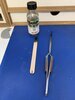
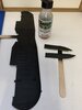
The a.m
View attachment 396935

There are only 5 sprues including the transparencies.

Here is one
View attachment 396936

Look at the fine detail
View attachment 396937

The instructions
View attachment 396938
View attachment 396940

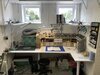
My bench all cleaned up and ready.

View attachment 396939
 

Attachments

  • 7BA10625-737B-4D19-841D-1F40EA4ABCD2.jpeg
    7BA10625-737B-4D19-841D-1F40EA4ABCD2.jpeg
    3.3 KB · Views: 0
  • 413E0211-5856-4765-91DB-29FC9BBDE958.jpeg
    413E0211-5856-4765-91DB-29FC9BBDE958.jpeg
    3.8 KB · Views: 0
  • 7D0F7EA7-2586-4BCE-AACD-E149906AE740.jpeg
    7D0F7EA7-2586-4BCE-AACD-E149906AE740.jpeg
    3.1 KB · Views: 0
  • 79A50A54-CDD7-4070-8938-D4692B746E4B.jpeg
    79A50A54-CDD7-4070-8938-D4692B746E4B.jpeg
    3.5 KB · Views: 0
  • D567605C-E3CF-4C22-B338-112FCA1A40BA.jpeg
    D567605C-E3CF-4C22-B338-112FCA1A40BA.jpeg
    4.2 KB · Views: 0
  • 1CF892C6-6CF4-45B3-95B2-3C2A743EA71E.jpeg
    1CF892C6-6CF4-45B3-95B2-3C2A743EA71E.jpeg
    3.9 KB · Views: 0
  • 442E6ECB-14E8-4EC0-85A0-E7A9C458A78E.jpeg
    442E6ECB-14E8-4EC0-85A0-E7A9C458A78E.jpeg
    3.6 KB · Views: 0
I was looking at the stash list in your signature on the completed bf110 and hoping this would be up next. I quite like ICM kits not overenginered but still nicely detailed.
 
Barry,
I'll watch with interest, but for some reason, the Gladiator doesn't appeal to me - but the future release by ICM of a Fiat CR 42, that's a different matter! :thumb2:
Dave
 
Barry

That does look like a nice kit and as always I'm in awe/jealousy of your bench!!

ATB

Andrew
 
Oh goody goody gumdrops! Like Karl, I was hoping this would be next. Are you going to do a full build post like you did with your Bf110?
 
Hi Barry
Great looking kit and I'm certain you will do it proud. Like Dave I enjoyed the extra detail posts in your BF110 thread although I do appreciate the time it takes.
I Googled Marmaduke Thomas St John Pattle, DFC & Bar, quite a story.
Jim
 
Thread owner
Thanks everyone. Yes I will do a detailed thread.

Speaking of which I will be trying these for the first time instead of my usual favourite Mr Cement S and De Lux.
View attachment 397001
I have only used the extra thin once on the tail planes and I like it, it’s at least as good as MCS and I like the small brush for precise application.

I don’t normally do this but I decided to remove the main parts, clean them up and test fit. I am working out the best way to deal with the rigging.

View attachment 397002
View attachment 397003

As you can see it’s a perfect fit in all respects. The plastic is nice, but a little thin.

The aerial mast on the fin won’t last 5 minutes, so I decided to cut it off and replace it now with a piece of brass rod.
I also need to use some brass rod for a mast on the top of the top wing. I am also working on drilling holes for the rigging. It’s slow and careful work to get all the positions right but it will pay off later.
View attachment 397004
View attachment 397005
View attachment 397006
View attachment 397007
View attachment 397008
 

Attachments

  • 2BCC3C7C-99C9-4C94-87E7-68847414800A.jpeg
    2BCC3C7C-99C9-4C94-87E7-68847414800A.jpeg
    3.2 KB · Views: 0
  • E4A5FE5F-AAA6-41AD-84E6-CBAD5E714860.jpeg
    E4A5FE5F-AAA6-41AD-84E6-CBAD5E714860.jpeg
    3.5 KB · Views: 0
  • 886C8488-53F3-433C-92EE-D928D46C2D08.jpeg
    886C8488-53F3-433C-92EE-D928D46C2D08.jpeg
    3.4 KB · Views: 0
  • 95BA995A-646C-4FBE-B679-3C2E5778DC2E.jpeg
    95BA995A-646C-4FBE-B679-3C2E5778DC2E.jpeg
    2.4 KB · Views: 0
  • DC616208-B6C1-4A23-A8E8-56DAA7E79374.jpeg
    DC616208-B6C1-4A23-A8E8-56DAA7E79374.jpeg
    2.6 KB · Views: 0
  • 67081B01-F97B-4602-8E78-646B6B23F352.jpeg
    67081B01-F97B-4602-8E78-646B6B23F352.jpeg
    2.4 KB · Views: 0
  • 5271765D-B384-41BD-BCA8-BB3F3AA73F08.jpeg
    5271765D-B384-41BD-BCA8-BB3F3AA73F08.jpeg
    3.3 KB · Views: 0
  • 182AD7BD-5396-4AF8-8B1D-47679CFD466D.jpeg
    182AD7BD-5396-4AF8-8B1D-47679CFD466D.jpeg
    2.3 KB · Views: 0
Thread owner
In the end I counted 51 holes that had to be drilled for rigging. plus two more for brass rod.

I also got on with some internal subs.
AD677345-3426-43DB-A107-F368F5055A94.jpeg
You can make out the holes..... it seemed to take forever.

07506CD0-E05B-4BFF-9952-C6A7E7A09008.jpeg

the machine gun above can be fitted after painting but on the other side i will have to leave off that internal framing until after painting as the mg needs to be fitted first. This is the value of dry fitting and testing....

C755C45C-917F-4E64-8D26-12EA589334E0.jpeg

there are quite a few subs to do before painting the internals.

In respect of the rigging I will be painting the underside of the top wing then attaching the rigging to it before cementing the top side of the wing. There will need to be some paint touch up when I have dealt with the seam but it will make the rigging easier needing only to attach it to the lower wing/fuselage. The tail rigging and arial rigging will be done as part of final fittings.
 
Thread owner

Attachments

  • 88842462-6EE8-4FEB-AE5D-E5B52FA6475D.jpeg
    88842462-6EE8-4FEB-AE5D-E5B52FA6475D.jpeg
    3.9 KB · Views: 0
  • CA7CAC34-C676-4E54-8CB6-6A4D2A05D3F3.jpeg
    CA7CAC34-C676-4E54-8CB6-6A4D2A05D3F3.jpeg
    2.2 KB · Views: 0
  • D25955E4-9953-46AF-99DF-D8CFC6BA093D.jpeg
    D25955E4-9953-46AF-99DF-D8CFC6BA093D.jpeg
    3 KB · Views: 0
  • 4C955CAB-BE49-4FD9-BD81-606AD74314F8.jpeg
    4C955CAB-BE49-4FD9-BD81-606AD74314F8.jpeg
    2.9 KB · Views: 0
Thread owner
I am making the most of the last couple of week that I will be home mid-day week and I have progressed nicely.

I have fitted the rigging to the underside of the top wing.
8D4FBEDF-BCA7-42B0-A7AD-17065DC449E4.jpeg
The rigging at the ‘glued’ ends do not create any fit issues for the top part of the wing. I have checked. OK when the seams are dealt with there will be some touching up of the underside aluminium but that wont be a problem.

Here is the underside
47C56431-62EF-4E7B-8E42-4AF7B944E2BA.jpeg

I used the heavy EZ Line which is perfect for this thanks to its stretch. Apparently the turnbuckles on a Gladiator are on the inside with the rigging lines going in through holes so that makes life a lot easier.

I have also been getting on with cockpit sub assemblies. After spraying the base colours I applied i.p. decals. ICM provide some excellent individual dials that lay down beautifully. Some of the best instrument dials I have seen. That was followed by a dark brown enamel pin wash. I then sprayed a matt varnish and followed up with dry brushing Uschi Metal Powder. Some earth pigment was also brushed onto the cockpit floor.

I did have one issue - the control column pinged off into the ether. It is not particularly small but I could not find it anywhere so I had to scratch a control column and I think it worked out quite well.

CE3E36F6-EFF8-4D3F-89E1-1037DA2755E0.jpeg

The dials were gloss varnished to simulate glass

EBB86764-5CE2-452E-B2A2-7113FD223D7F.jpeg

The steel seatbelts were an easy fit. The shoulder belts are fitted once the seat in in place in the fuselage.

One of the fuselage sides.
E6B06B6B-DCDD-4541-9062-64F5AFCA312B.jpeg
 
Hi Barry
As always neat and well planned work. Forward planning with the rigging makes so much sense. Do the instructions include advice for the rigging or do you just go by references and the box art? Is the primer for metallic finishes gloss or matt?
Jim
 
Thread owner
Hi Jim. The primer works for either and there are full rigging details in the instructions.
 
Thread owner
A fair bit more progress..

the cockpit before joining fuselage halves
D0987800-64B1-4004-8EC8-4D7833B4DFD1.jpeg

EDA7AA26-94DD-486F-9C51-4EA2DEDB6B71.jpeg

Here the lower wings are attached. Perfect fit as always with this kit.

FB1713BA-46EC-4B97-B4AD-EBC629DC3A76.jpeg

I dry brushed Uschi Metal Powder onto the propeller boss. I believe that the prop is wood so I kept the metal powder off that. I am still debating how to ŵeather the wood prop, a dry brush with light brown pigment perhaps. Any suggestions on that one...

EC3EB766-D5FF-481D-BD12-161FBD414D10.jpeg
Also, for the next build, the Sea Gladiator, with a three bladed prop, I assume that was wood as well. Does anyone know for sure?

A bit more fuselage work.
88DFFFF6-7DA4-4E09-8C25-A7092F112516.jpeg

Finally a start on the very nice engine.

85300C5A-6A23-4B59-A960-6B609B41856E.jpeg
 
I dry brushed Uschi Metal Powder onto the propeller boss. I believe that the prop is wood so I kept the metal powder off that.
(…)
Also, for the next build, the Sea Gladiator, with a three bladed prop, I assume that was wood as well. Does anyone know for sure?
The Wikipedia article on the Gladiator says:—
The Mk II soon followed, the main differences being a slightly more powerful Mercury VIIIAS engine with Hobson mixture control boxes and a partly automatic boost control carburettor, driving a Fairey fixed-pitch three-blade metal propeller, instead of the two-blade wooden one of the Mark I.

IPMS Stockholm has it like this:
Both the Mk II and Sea Gladiator were originally built with the three-bladed metal propeller, but most had these replaced by the original two-blade wooden prop in service.

Also, this line may be of interest for your build:
Something that should be mentioned is that RAF wooden propellers were painted a shade of grey very similar to Medium Sea Grey - this I know from having seen many original examples during the time I worked for the RAF Museum.
 
Thread owner
More progress and getting to the trickier part of the build.

the gunsight attaches. Nicely fits into place
6E9AD4C2-C4C9-41AE-82BA-38302C6C2417.jpeg

Front and rear canopy transparencies
67147455-2B4A-4448-BDA0-2DB56C29E192.jpeg

engine coming together. There are some ‘tripod’ structures to fit into place so I cemented in the two inner legs and I will, when dry, superglue the outer leg. Superglue because they will need to be held in place until the glue grips.

70ADA606-B933-41FE-8294-1D6FBBC4A98E.jpeg

I have used tape to hold the rigging lines out of the way
10867224-19F9-4C83-AFA5-1BC4720EF8F2.jpeg
21614FD0-3D9E-4AAF-A5B8-DA0338E7AF0F.jpeg

I won’t be cementing the top wing into place until the model is painted but I will need to use it to get the uprights into position.

The very dark grey wooden prop was dry brushed with a brown pigments.
76898DF1-F50F-4E70-90F7-2D413444DF97.jpeg

Below the canopies are drying awaiting the fitting of the wing pylons, I am planning to use a slow drying cement on the four outer ones then I will position the top wing without cement to get it in the right position. Once the outer pylons are firmly fixed in place I will tape the top wing into position to hold it while fitting the inner pylons and cementing them to the fuselage only. When those are dry I will remove the top wing and, using tape, I will swap the rigging to be held out of the way on the underside ready to paint the top.

42EFE232-EDE5-4F90-B62D-1B260A9A8A91.jpeg
 
Thread owner
Biplane builders please Help!

It don’t work and I dont know what to do!!

I did what I said and found I had great difficulty getting the top wing on, when I did it was incredibly rickety and I could not get it into position and hold it for the glue to dry at the right angles.

I quickly had to remove all the struts before they dried in the wrong positions.

So I tried to tape them to the underside of the wing and then dropped some slow drying cement into the locations and position the wing. Same problem.

So, how on Earth can I do this? I have no idea at all.

My only other biplane was the Swordfish and I think that there was a positive firm location to get it started. No such luck here, not the fault of ICM but because the aircraft was not constructed in a way to facilitate that.

3067B1FE-8588-4613-AA15-E670F4C6D815.jpeg

B1F141C9-97A3-484A-92CC-026F2AA100A9.jpeg

I am left with a bit of a cement mess Olin the location holes to sort out.
DEB54BCA-3096-4DCC-9F45-F0D86190A6AB.jpeg
 
I saw the attached where a makeshift jig was cut to suit plane and then skewers or slim sticks poked into it to hold everything in place. Never tried it myself but looked like it worked.468158C7-769A-484F-8360-08476AE29381.png
 
Back
Top