Theme editor

Scale Model Shop

Italeri Kfz 305 Opel Blitz with Tamiya 20mm Flak 38 MIT Sd.Ah.51

Thread owner
Hi Everyone

Scottie - As you know the devil is in the detail:thumb2:
Jim - Keep taking the pills mate:tongue-out3:
Pete - I used to use milliput for sheeting put found foil a lot easier to use
Peter - Cheers mate
Colin - Great to have you along for the build and thanks for the support:thumb2:
 
Thread owner
Hi Everyone
Well after melting in the back garden all day it was nice to cool down with some bench work today

Firstly the pick axe holder was done. Then the Opel mascot on the bonnet was added along with the front hooks and number plate. Chain or rope will be added onto the hooks at the end of the build. This then completed the front cab
View attachment 300252View attachment 300253View attachment 300254View attachment 300255

Next comes Section 3 which deals with the under carriage

View attachment 300256

The rear axle is incorrect and lacks detail. This is what the kit gives you

View attachment 300257

The central hub needs to be oblong not round so the edges were removed. Fresh ribs have been added, sanded down and filled. This will be left to dry over night before a final sanding is done. A dozen bolt heads also need to be added

View attachment 300258View attachment 300259

On the other side I added the bolt heads using Johnsons Klear

View attachment 300260

While this was all drying I jumped ahead and made a start on the wheels. As always the rubber tyres had rubber flash all the way around the tread. Also the grooves of the tyre are incorrect. However the resin sets are so expensive I will just have to live with this mistake

View attachment 300268

So I set about removing the flash. I gently shave the tyre with a razor and then remove the leftovers with steel wool

View attachment 300261

View attachment 300262

The problem with no sprue numbers hasn't been an issue until now. These are all numbered differently and there are subtle differences on each one. Anyhow thats tomorrows problem:hugging-face:

View attachment 300263

Thanks for watching

Steve
 

Attachments

  • IMG_0045.JPG
    IMG_0045.JPG
    3.9 KB · Views: 0
  • IMG_0043.JPG
    IMG_0043.JPG
    2.6 KB · Views: 0
  • IMG_0044.JPG
    IMG_0044.JPG
    3.2 KB · Views: 0
  • IMG_0039.JPG
    IMG_0039.JPG
    2.6 KB · Views: 0
  • IMG_0040.JPG
    IMG_0040.JPG
    2.2 KB · Views: 0
  • IMG_0038.JPG
    IMG_0038.JPG
    2.4 KB · Views: 0
  • IMG_0037.JPG
    IMG_0037.JPG
    2.6 KB · Views: 0
  • IMG_0036.JPG
    IMG_0036.JPG
    2.2 KB · Views: 0
  • IMG_0048.JPG
    IMG_0048.JPG
    3.1 KB · Views: 0
  • IMG_0047.JPG
    IMG_0047.JPG
    3 KB · Views: 0
  • IMG_0046.JPG
    IMG_0046.JPG
    3.2 KB · Views: 0
  • IMG_0041.JPG
    IMG_0041.JPG
    2.7 KB · Views: 0
  • IMG_0035.JPG
    IMG_0035.JPG
    3 KB · Views: 0
Hi Steve,
I may have missed this one previously, but now I am catching up. Excellency at its best. I am always amazed with your skills and detailed work. Looking forward for more and more :tongue-out3:
 
Hey Steve,
I finally found this as I have been searching all over for it. It wasn't under where you said you put it and not in the other normal categories either. No biggie Bro!!! Nice bling and this is turning into another super build. I will be following this from now on. Please don't move it someplace else, ok???
Prost
Allen
 
Thread owner
Marcello - Great to have you here. thans for the positive comments
Allen - Glad you found me. I have been a lost soul for far too long now:smiling3: I will make sure I dont move her again:thumb2:
 
Just had a read through - off to a good start

Don't forget that the master leaf spring has rolled ends so the roll part doesn't sit on top of the leaf, it is part of the leaf itself
 
Steve,

Nice work so far, try a scotchbrite type scourer for the rubber wheels. I find it gives a better abrasive action than the steel wool.
Scottie
 
Hi Steve
Amazing stuff Sir. Mad as a box of frogs but still amazing. Just love the rolled up roof. And as for the 10 leaf spring - great.
Jim
 
Thread owner
Hi Everyone

MrT - I saw that. I have sanded them down as best as possible but it doesn't look like one solid piece. I will try again
Scottie - I will try that as wire wool gets everywhere:thumb2:
Jim - More madness to come. Sadly Matron is late bringing my pills again:smiling3:

Well after a day roasting in the garden it was nice to cool down with a little bench time. Firstly I would like to start with a mini rant. I would luv to go to a kit manufacturing plant and find out how the moulding process is designed. I can deal with seam lines. I can deal with flash. I can even deal with the odd badly formed part but injector marks on the front of parts that are clear to see??!! How difficult can it be to put the marks on the back of the part out of sight of the viewer. This seems to happen all the time

View attachment 300473

Any way rant over. The injector marks have been filled and sanded. The wheels went together well. They even supplied a spare for under the chassis

View attachment 300474

I completed the detailing on the rear axle with the completion of the ribs and the addition of some bolt heads

View attachment 300476

I still cant bring myself to finish the springs so I jumped to the next section which deals with the engine parts

View attachment 300477

I am no engine person and all the parts will be fitted as is. However if you want to detail the engine this is a good base to work from. None of this can be fitted until I finish the chassis detailing so it was onto the rear floor

View attachment 300478

This is the blank canvas that the kit offers you

View attachment 300479

Firstly the wood parts are heavily sanded with the coarsest sand paper I have. Then I sawed off the back end

View attachment 300480

Next I added wood grain to the planks with heavy marking with a craft knife at each end. The a few grooves along the length of the plank

View attachment 300481

However at the sawn off end I went to town on the grooves adding as much damage as possible. Then the rear end was reattached giving a nice worn out look

View attachment 300482

Thats it for today. Thank you all for your continued support

Steve
 

Attachments

  • IMG_0049.JPG
    IMG_0049.JPG
    2.9 KB · Views: 0
  • IMG_0052.JPG
    IMG_0052.JPG
    3.2 KB · Views: 0
  • IMG_0058.JPG
    IMG_0058.JPG
    1.7 KB · Views: 0
  • IMG_0057.JPG
    IMG_0057.JPG
    1.7 KB · Views: 0
  • IMG_0056.JPG
    IMG_0056.JPG
    2 KB · Views: 0
  • IMG_0055.JPG
    IMG_0055.JPG
    1.6 KB · Views: 0
  • IMG_0053.JPG
    IMG_0053.JPG
    2.9 KB · Views: 0
  • IMG_0054.JPG
    IMG_0054.JPG
    2.3 KB · Views: 0
  • IMG_0051.JPG
    IMG_0051.JPG
    1.9 KB · Views: 0
Homemade springs very nice Steve and good job with the hood hooks.:thumb2:
Great woodwork too, keep it coming.:cool:

Fernando
 
Hi Steve sorry for being stupid, you added the bolt heads to back of the diff housing using Johnsons Klear, what as a glue ???
Pete.
 
Seems like someone really likes etch and extra detailing ey ^^. Nice build Steve, and what an original way of trimming the mould seams on wheels :smiling2:

Cheers
 
Thread owner
Hi Everyone

Fernando - Springs are on the sidelines at the moment as my attentions are being diverted elsewhere:smiling3:
Pete - That's right. It's ideal for difficult to reach places. You need to apply a couple more coats once dry. Its far from perfect but the ease and lack of glue stains does make it appealing
Wouter - Cheers mate. Some bling on its way:cool:

Sorry everyone but I have had no time this week to do regular updates so here we go

First heat damage was added to all the fenders. This will become more evident during the painting phase

View attachment 301108

The PE rear mud flaps were made up and added to the mudguards

View attachment 301109

The rear number plate was replaced with a selection of PE items and a strip of plastic. The number plate was bent up. When the decal is applied it's quite a good look. Certainly better than the kit offering on the left

View attachment 301110

If you look on the original photo there is a row of jerry cans on the L/H side. However there was a lovely PE box which I decided to make and put there instead. So I have moved the jerry cans to the other side

View attachment 301111

The rear kit boxes are nicely detailed. So rather than replace the padlock and clasp I left as is and just added hinges and brackets

View attachment 301112

In between these boxes is a PE jerry can holder. I have made this up and put in a captured American can from the battle at Kasserine pass. I also added a pin and chain for interest

View attachment 301113View attachment 301114

Next I turned my attention to the make shift jerry can holder. The picture showed seven cans. So I made these up and checked to see if they would fit

View attachment 301115

Next I stuck them all together with two decent ones at the ends

View attachment 301116

The easy way to make the frame would be to just stick the strips of plastic to the cans. However I wanted to create depth so I built the frame around the cans. I used styrene strip and brackets

View attachment 301117

Then I added strengthening bars at each end and then a holding bar all the way around the centre of the cans

View attachment 301118

I added a padlock and rivets for extra detailing

View attachment 301119View attachment 301120


View attachment 301121

So now I have a drying table with a lot of components that all need to be put together. However firstly I need to look at making the sledge.

View attachment 301122

Thanks for watching

Steve
 

Attachments

  • IMG_0063.JPG
    IMG_0063.JPG
    2.9 KB · Views: 0
  • IMG_0064.JPG
    IMG_0064.JPG
    2.9 KB · Views: 0
  • IMG_0062.JPG
    IMG_0062.JPG
    3 KB · Views: 0
  • IMG_0061.JPG
    IMG_0061.JPG
    3 KB · Views: 0
  • IMG_0060.JPG
    IMG_0060.JPG
    2.7 KB · Views: 0
  • IMG_0059.JPG
    IMG_0059.JPG
    3.1 KB · Views: 0
  • IMG_0058.JPG
    IMG_0058.JPG
    2.9 KB · Views: 0
  • IMG_0057.JPG
    IMG_0057.JPG
    2.6 KB · Views: 0
  • IMG_0056.JPG
    IMG_0056.JPG
    2.9 KB · Views: 0
  • IMG_0053.JPG
    IMG_0053.JPG
    2.8 KB · Views: 0
  • IMG_0054.JPG
    IMG_0054.JPG
    2.6 KB · Views: 0
  • IMG_0052.JPG
    IMG_0052.JPG
    2.6 KB · Views: 0
  • IMG_0051.JPG
    IMG_0051.JPG
    2.8 KB · Views: 0
  • IMG_0050.JPG
    IMG_0050.JPG
    2.5 KB · Views: 0
  • IMG_0049.JPG
    IMG_0049.JPG
    2.9 KB · Views: 0
Evening Mr Steve,
Ever so sorry for missing so many updates. I’ve just had a thoroughly good catch up with all yer mods and extra odds and sods.
Very impressed with how the tyres turned out....I’d never of thought to rough em up, they look good like that.
You’ve done loads to improve this kit...I only did some PE on my Italeri one as a practice piece but you’ve really gone the whole hog:thumb2:
Keep it rolling mate. If you want any more pics give us a shout:smiling4:
Si
 
Whoah...after going through the pages I need to rest my eye from all that bling. This is what happens when you miss so many updates.

Steve, must you detail the undercarriage as well...you're killing me. Overall fantastic work.:thumb2:

Cheers,
Richard
 
Steve.
You are indeed related to Mr T with out doubt !
Mad as a box of drunk frogs ,but I like you.:hungry:
Matron will be around later to tuck you in.:flushed:
Blown away mate, just amazing .
JR.
 
Thread owner
Hi Everyone

Si - Thanks for the offer mate:thumb2: You know me, I like to add lots of detail:smiling3:
Richard - I am thinking of doing all the wiring on the under carriage as well but we will see how I feel when I get to it
JR - Sadly not mate as I am a southern softy. However I am certifiably madder than Mad Jack McMad, the winner of last year’s Mr Madman competition:smiling5:

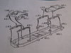
Well today has been a rewarding day at the bench. The task was to scratch build the sledge for the flak unit to go on. I have unashamedly copied Ron Lebert's wonderful blog that he did in 2010 on the site with no name about how to build the sledge. Although not as good as his, and despite the disaster at the end, it hasnt turned out to bad.

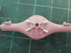
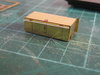
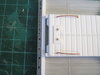
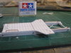
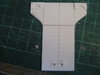
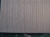
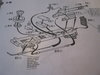
So firstly we need a base.

View attachment 301169

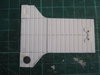
Following Ron's hand made scale drawing of the base, I cut a piece to the right size and added a central line to work off.

View attachment 301170

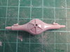
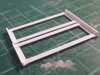
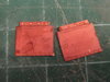
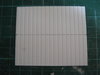
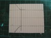
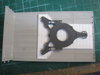
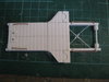
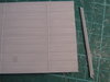
I then drew on the shape that needs to be cut away. I dont have the correct tools to do this exactly so I used free hand and then sanded it into shape.

View attachment 301171

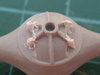
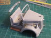
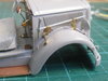
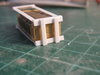
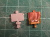
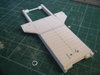
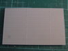
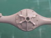
I then checked the Flak base would fit in position okay:thumb2:

View attachment 301172

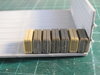
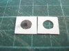
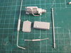
Next I made the stops for the three feet on the Flak base. I dont have a drill bit this size so again this was done free hand and they came out "okay"

View attachment 301173View attachment 301174View attachment 301176

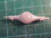
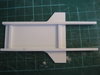
Next I had to build a simple frame underneath. I did not have the correct size struts so I doubled up the ones I had and glued them together

View attachment 301177

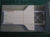
These were then cut to size according to Ron's instructions, sanded and glued into place. I also added a couple of supporting struts

View attachment 301179

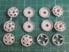
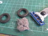
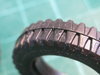
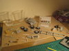
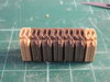
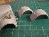
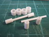
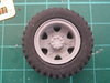
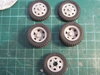
Next the rollers were made from these parts. One day I will learn how to cut a piece of tubing straight:smiling2:

View attachment 301180

These were then put at the front and end of the sledge. There should be one in the middle but as this will not be seen I didnt bother

View attachment 301181

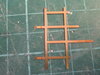
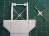
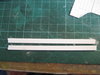
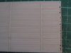
Next I attempted the criss cross support at the top. My first effort on the R/H side was to thick. So I cut a smaller strip and this looked far better

View attachment 301182

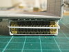
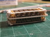
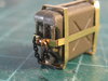
Final detailing was added with copper handles, bolt heads and rivets

View attachment 301183View attachment 301184

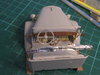
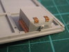
I then put it onto the truck and DISASTER! It was too long!!. Ron had designed his sledge to go up against the back board of the truck. I actually needed mine to be shorter and supported by a plank of wood bolted onto the floor.DOH! So I had to go all the way back to the beginning and build another one. Yeah - that aint happening:thinking:. So I cut 7mm off the end and redid the handles which I was happy to do as I was not happy with the first ones. The cross members were left as is so it's a little out of proportion. However if we dont tell any one we should get away with it:tongue-out3:

View attachment 301185

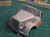
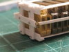
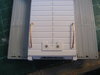
So as you can see it fits as it should do and the support plank will fit okay now and it still leaves the damaged plank ends showing:thumb2:

View attachment 301186View attachment 301187

The support planks around the outside will be tomorrows challenge

Thanks for watching.

Steve
 

Attachments

  • IMG_0095.JPG
    IMG_0095.JPG
    2.3 KB · Views: 0
  • IMG_0079.JPG
    IMG_0079.JPG
    1.8 KB · Views: 0
  • IMG_0078.JPG
    IMG_0078.JPG
    2.1 KB · Views: 0
  • IMG_0080.JPG
    IMG_0080.JPG
    2 KB · Views: 0
  • IMG_0082.JPG
    IMG_0082.JPG
    2.6 KB · Views: 0
  • IMG_0083.JPG
    IMG_0083.JPG
    2.5 KB · Views: 0
  • IMG_0094.JPG
    IMG_0094.JPG
    2.1 KB · Views: 0
  • IMG_0093.JPG
    IMG_0093.JPG
    2.2 KB · Views: 0
  • IMG_0092.JPG
    IMG_0092.JPG
    2.9 KB · Views: 0
  • IMG_0091.JPG
    IMG_0091.JPG
    2.3 KB · Views: 0
  • IMG_0090.JPG
    IMG_0090.JPG
    2.7 KB · Views: 0
  • IMG_0089.JPG
    IMG_0089.JPG
    2.6 KB · Views: 0
  • IMG_0088.JPG
    IMG_0088.JPG
    2.8 KB · Views: 0
  • IMG_0087.JPG
    IMG_0087.JPG
    2.2 KB · Views: 0
  • IMG_0085.JPG
    IMG_0085.JPG
    2.6 KB · Views: 0
  • IMG_0086.JPG
    IMG_0086.JPG
    2.2 KB · Views: 0
  • IMG_0084.JPG
    IMG_0084.JPG
    2.1 KB · Views: 0
Steve.
A cunning piece of scratchery indeed. The wood work dept here at Race Towers are highly impressed with the timber work on the bed.
JR
 
Back
Top