Theme editor

Scale Model Shop

Scratchbuilt 1/72 Avro Aldershot

Steve-the-Duck

Active member
SMF Supporters
Joined
Jul 3, 2020
Messages
1,812
Reaction score
127
Points
63
First Name
Chris
Location
Medway Towns
1/3
Thread owner
I could have added this to the completed thread, but I've a LOT of pics of the build. And no-one said you can't do the WIP stuff first

So, this was three months work, copious amounts of 10, 20 and 30 thou plasticard, a couple of missteps, a LOT of careful planning and doing things in the wrong order, but overall, I'm very pleased with the result. And it's not like anyone is going to kit this beast any time soon
And if they do, I can always convert it to an Andover transport
IMG_3699~2.webpIMG_3683~2.webp

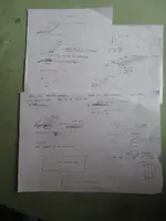
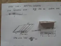
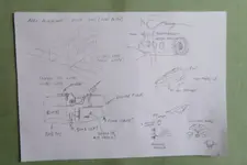
Starting off, sketches drawn from online pics, specifically Rex's Hanger Aldershot feature on Youtube. At the time, back in April, I didn't have a means to capture and print pics. Next there's the 'how to go about each piece.' This is the final layout, as I kept adding new stuff as I went
IMG_3613.webp
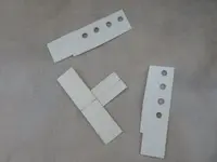
And this is where we start with the two main fuselage sides and the base (with 'main spar') already attached
Now, if I can only get the rest of the photos uploaded and accessible...
 
Thread owner
And we're up and running
IMG_3617.webp
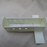
So, the crew cabin altogether, with a few spars added for detail. At this stage I already knew the interior when finished would be practically invisible, but hey...
IMG_3620.webpIMG_3619-1.webp
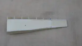
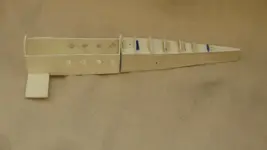
The tail box, interior structure and side panels
IMG_3621.webpIMG_3622.webp
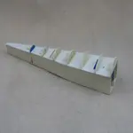
Added formers for the upper surface shape. So far, everything was 20 thou plasticard
IMG_3629.webp
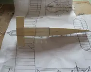
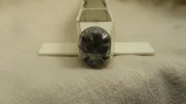
Tail assembly attached to the main cabin. It was all going well this far. Then I realised the amount of weight that would be on the butt joint between the two parts, what with all the tail surfaces to be added, so I later fitted two 1.2mm brass rods as support

IMG_3631~2.webpIMG_3632.webp
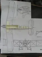
The scale plans I used are blown up photocopies from the Puttnam Avro book. Nothing wrong with my maths with the percentage increase; basically, what are the 'real' dimensions in 1/72, and how big are the pics
Sorted
 
Thread owner
Very nice work Steve. It will be a nice addition to your collection when completed 👍
Well, technically it already is. I've already posted the pics in the completed thread. But for best results, follow here and then go check out the outcome!
 
Thread owner
Okay, next
IMG_3636.webp
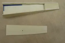
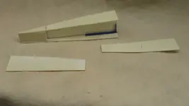
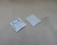
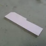
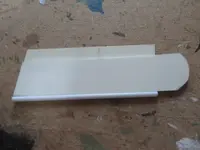
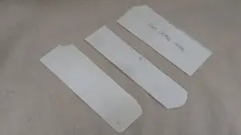
These are the paper and card templates for the rear fuselage upper decking. Measure five times, cut twice, which eventually lead
IMG_3634.webp
to this. All the skinning of the model is 10 thou plasticard, scribed on the inside to make ribs. Still needed fettling afterwards, but this was only the second attempt in plastic

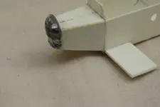
Then onto the tail surfaces. The body is 20 thou card again with the 10 thou skinning
IMG_3649.webpIMG_3655.webpIMG_3656.webp
Support struts are my ubiquitous Aeroclub stut material, which I REALLY need to find more of. Naturally, the struts got a bit knocked about a bit through the rest of the build, and one of the elevators came off, and stayed off thill MUCH later
Also, the tail surface is supported by a piece of brass rod, and at this stage a long tail fin, which I later realised is only on the Mk.I prototype, so that got cut off later
IMG_3650.webp
The rudder, which was left off almost to the very end, is a !0-20-10 sandwich. Not my first attempt at this either, as my Breda Ba.44 from waaay back will attest.
 
Thread owner
Now, the wheels are one of the few parts from somewhere else. I don't have a method of making big circular pieces so
IMG_3651.webpIMG_3654.webp
These, would you believe, are road wheels off an OLD Tamiya Panzer II!
 
Thread owner
So, would you believe the nose piece is an old 3D support piece?

IMG_3645.webpIMG_3647.webpIMG_3648.webp
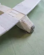
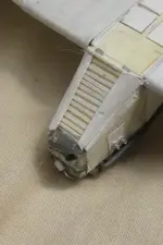
A bit of fettling, filling and venting, plus a road wheel off a 1/72 Lorraine 37, and the nose is in place, on a simple box of plasticard
Later, I will realise that the whole nose piece is mounted 4mm too low. The base should NOT align with the fuselage bottom!

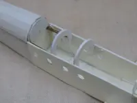
Now, here we have the Cockpit formers in place, plus the brass support rods for the tailIMG_3653.webpIMG_3652.webp
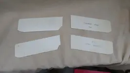
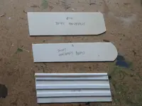
And the card templates for the cockpit coaming. Wait! It says that on the template!
 
Thread owner
So, here's the tail after removing, cutting back the fin, and re-attaching, with the brass rod at the centre plated either side
IMG_3662.webp

Next, things starting to go mildly astray, all of my own making, I might add
IMG_3657.webpIMG_3658.webpIMG_3660.webp
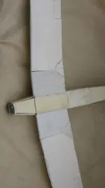
My original plan was to have the port wing folded, so as to take up less room on the shelf, hence the centre section attached to the main spar and fuselage. The mistake I didn't realise was putting the upper surface of the wing on first, rather than the bottom. This meant later I had to add plates the upper section to get a better thickness. And it was such a nice aerofoil section too!
 
Thread owner
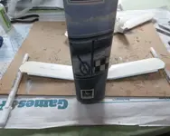
The first attempt at building one of the outer wing panels, in a 30 - 20 thou sandwich. Which I realised rapidly was going to be way to heavy. I was always intending to put on a 10 thou skin with rib detail anyway, but...
IMG_3661.webp
So, with a bit more thought and planning, A lighter solution was rapidly achieved
IMG_3663.webpIMG_3666.webp
 
Thread owner
'May I say, sir, that now we are cooking with gas'

IMG_3668.webp
These are the centre pieces for the outer wings, upper and lower, with a message to myself to get them the right way up. I mean, I wouldn't want to end up with two port upper wings, and no starboard!
The cut-outs on the port wings were for the folded layout. I was already wondering how practical that was with the amount of weight to support
IMG_3669.webpIMG_3671.webpIMG_3672.webp
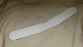
So here's the simplified wing construction as in the diagram. A centre panel with a pipe leading edge, cross-spars in 40 and 30 thou strip, and a 20 surface for the 10 thou skinning to go on. I did think I might get away without the 20 sheet, but the scribed-ribbed 10 skin would show up the formers underneath, as was just visible on the tail upper skinning
 
Thread owner
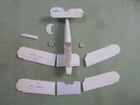
So, here's all the main parts together by this stage. The wheels have already been thinned and shaped, with a circle of 10 thou on the back to simulate the tyre shape
IMG_3674.webp
Note, I also had the idea of making entirely separate control surfaces, but with the new win g structure shown here, I'd already ditched that idea
IMG_3677.webp
So, this was my method of getting the upper wing dihedral. Puttnams weigh a tonne! The bonus of using a tube as leading edge is the brass rod to support the weight overall, fits nicely without too much aggravation. As you can probably tell, I'd abandoned the idea of the wing fold

IMG_3675.webp
And here's the lower wing attached, and you can see some of the plating and filling I've done to get the centre section to conform to the aerofoil shape of the outer panels
IMG_3676.webp
So now it was all coming together. What could go wrong now?
Well, truth be told, not much after this!
Stay tuned...
 
Last edited:
Thread owner
You can see here the lower wings formed pre-skinning IMG_3679.webp

Here's the upper wing skinning pieces before rib-scribing. I went for wraparound pieces which worked out pretty well
IMG_3685.webpThe upper wing with centre section skinned. I went for separate pieces for the control surfacesIMG_3684.webp

IMG_3686.webp
And that's the lower wings fully skinned, with insert pieces covering the folding section
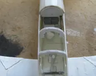
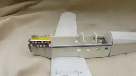
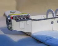
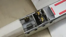
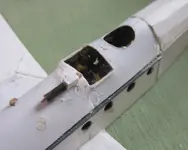
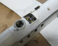
The big grey boxes in the back of the cabin are to represent the radio transmitter and receiver. There are no interior pictures of the Aldershot I could find, and the side view drawings don't show the radio position at all. Later, I realised on the plan there's a big square hatch on top of the fuselage, behind the cabin, so the radio could have been in there, like on the Siskin. The side views also show a POSSIBLE ventral gunner position, right where I put the radio, but I've got it close to the centre of gravity, so that'll do

One of the unknowns about this 'plane is the crew number; Puttnams has it at 3, which would only be the two pilots and the gunner. There must be a fourth as a bomb aimer (who'd have a nightmare getting out of the 'plane in trouble, like through the bomb hatches!), and a radio op/gunner would be five!
 
Thread owner
The wraparound skinning works pretty well. And once all set, the trailing edge could be scraped and sanded thinner
IMG_3687.webp

I was going to use one of the unused seats from my vacform Hawker Horsley (which will get posts of it's own sometime), but they're not up to much, so I scrapped-up one from a pipe end and plasticard
IMG_3689.webpIMG_3690.webp
And in it goes, with a small nav table under the radios. The bomb sight, having researched early ones on the RAF's own history site, is a spare MG out of an old Airfix Ju.88 (which is my go-to for lots of interesting little bits and shapes!) with a few scraps of rod. Once again, the side interior view I've seen shows a very complicated bombsight, un like anything in service. Port side rear of the cabin is a piece of rod to emulate what MAY be a flare chute on the side view
 
Thread owner
And now onto the real scratchery
IMG_3691.webp
I didn't find a detailed pic of the Rolls Royce Condor engine, so I went with what's visible on the Puttnam plans and the photos. The cylinder heads are bits of 1/24 rocket ends, from the Airfix Mosquito (?), topped with the wheels from a 1/72 Lorraine 37L tractor. The piece on top of the engine is a spare bit out of a Hawker Hart. I knew when I put it on I should have pinned it for safety, as it was bound to get knocked off
Which it was!
All the piping is simply plastic rod
IMG_3693.webp
So, when I went to fix the exhaust pipe, it didn't have the correct kink in it. At which point I realised I'd mounted the nose too low by 3/4 mm, aligning it with the bottom of the fuselage rather than the top
D'oh
But, it came off easily enough and remounted fine
Next on was the huge under nose radiator. Lots of little strips
IMG_3694.webp
Also, not the bomb hatches and the bomb aimer's hatch
IMG_3696.webp
Couple of shapes to form the cowling, a back piece with some off-cut bits for, conjectural, vents
A photo also showed the inspection hatches had pipe vents sticking out of them, so that's another late addition
 
Thread owner
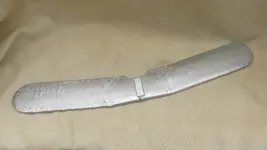
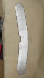
With my Silver Wings I try to completely finish the top wing first
IMG_3688.webp
Fully skinned and with the top tank added, out of a simple plasticard sandwich. Next the header-transfer tank was added to the front of the wing, made out of ubiquitous strut material

Paint! Simple rattle-can silver, with aluminium fr the tank bits. Pne side looks better than the other, but that's just the labour of the skin-scribing
IMG_3701.webpIMG_3702.webp
And THEN I've got to drill all the little holes for the strut and rigging mounting points! That may be the longest job after the skin-scribing

So, finally
IMG_3703.webp
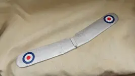
The roundels are out of my Modeldecal between-the-wars sets, which don't offer too many problems. Usually. One of these will later have to be replaced, but that happens
The roundels are actually for the Siskin. They're the largest ones of the correct colour and style I've got, all the rest are just too small for these gert slabs of wings. And I've enough left to do the Sisikin III, III and DC in the stash, so no worries
 
Back
Top