Theme editor

Scale Model Shop

SE5a CONSTRUCTION BEGINNING TO . . .

Status
Not open for further replies.
Thread owner
Tony

I know it works using seperate hydraulics because there is a reservoir for the fluid under the instrument panel. I’ve no idea about the technical details but it must be connected to the engine somehow to synchronise the firing to the prop speed. Maybe there's someone out there who can explain it to us!

Grahame
 
Here is a shot that shows the pump. It was driven by a gear on the prop hub. It had a 2:1 ratio and triggered the gun as each blade passed. Since the engine RPM was much faster than the gun could fire, as soon as a bullet was chambered it would fire through the first gap. This allowed it to fire at close to it's max rate.

View attachment 15535

View attachment 128061
 
Thread owner
Wot no pitot!


Of course not! What I failed to point out in my previous post was that I’d already made the pitot but I had no photo at the time because it was held together by masking tape while the epoxy cured.


View attachment 262975


The trouble with anything like this, which sticks out from the model, is that it is very susceptible to “hanger rash”. To alleviate the problem it has to be made strong enough to take a few knocks, removable or flexible; they all have their pros and cons but I tend to go for the first option, to that end it’s made from tin plate and copper tube. The “weak point” will be the fixings to the interplane strut so any substantial knock will break them and not the pitot or more importantly the strut.
 

Attachments

  • pitot 1.jpg
    pitot 1.jpg
    1.8 KB · Views: 0
Thread owner
Went to see Phil at Fighter Aces and bought the Warbirds paint, minus the PC10, which he hasn’t got in stock at the moment. It’s the first time I’ve used this paint, it’s quite thin with a flow more akin to ink than paint and it does take several coats to cover but overall I have to say that I’m very impressed with it. Water based so easy clean up, virtually no smell, quick drying and to top it all, fuel proof!


The model will be entirely brush painted and for the registration etc I’m using my preferred method of permanent marker for the outline. White lettering can be a problem as it’s quite difficult to get white marker pens but a bit of forward planning can save the situation. The area concerned is painted all over white first and the “background” painted in afterwards.


View attachment 262976


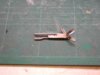
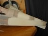
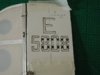
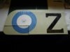
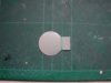
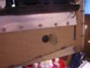
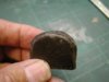
This will be a white “Z” on the top wing when I eventually get a coat of PC10 on. The under surface of the tail plane has been finished with “linen” paint.


View attachment 262977


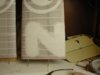
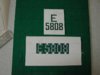
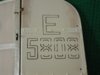
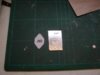
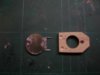
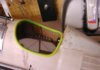
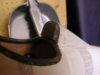
The registration markings are printed onto thin card and templates cut out leaving “bridges” where necessary.


View attachment 262978


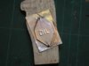
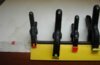
The top template above is for black lettering the bottom one for white lettering.


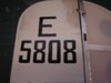
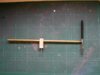
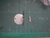
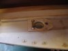
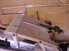
The template is held in position with “low tack” masking tape and the outline drawn.


View attachment 262979


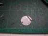
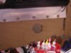
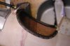
With the template removed the “gaps” can be filled in using the marker pen and a rule.


View attachment 262980


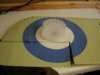
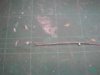
Use a fine brush for the edges and then fill in with a flat brush. At this stage they look “too good” but the final “weathering” will take away the “newness” and allow some of the white to show through in places.


View attachment 262981


I don’t worry too much if I stray slightly outside the lines; remember the original was painted well before the advent of masking tape and airbrushes! If, once all the painting’s finished, I don’t like the look of any part of the lettering then I’ll just do a bit more “weathering” around the offending area and it’ll soon merge in to look OK.
 

Attachments

  • painting 5.jpg
    painting 5.jpg
    2 KB · Views: 0
  • painting 4.jpg
    painting 4.jpg
    2.1 KB · Views: 0
  • painting 1.jpg
    painting 1.jpg
    2 KB · Views: 0
  • painting 2.jpg
    painting 2.jpg
    1.9 KB · Views: 0
  • painting 3.jpg
    painting 3.jpg
    1.9 KB · Views: 0
  • painting 6.jpg
    painting 6.jpg
    2.2 KB · Views: 0
I fully agree with your thinking Greyhead. So many people spray paint boat hulls and superstructures on models from the early 1900's long before boats were painted with spray guns!!

To make the model realistic paint with the closest you can to the original technique. My coaster is being painted with small flat brushes to simulate the large flat brushes used to paint the original ships and I will be making a point of 'feathering' the edges of the red and the black of the hull. As you say in those days who bothered with straight neat lines?!!
 
Thread owner
Richard

I couldn’t agree more, we can tend to “romanticise” these old aircraft etc. When we see examples today they have been painstakingly restored to “showroom” condition but at the time the SE5a was just another way to kill the enemy and being churned out as quickly as possible. To get an idea of how they must have looked it’s best to look at one of today’s “work horses” like a crop duster; no perfect paint job there!

Grahame
 
Thread owner
Before marking out the roundels a piece of liteply is taped at the centre position to hold the point of the compass, the circles drawn in pencil and the white blocked in. Then the circles are drawn again, this time using red and blue marker pens, I haven’t got a “PC10” pen for the outer ring. The centre red section won't be painted as yet, it’ll have to wait for the outer ring because I can’t remove the liteply until that has been drawn.


View attachment 263009


This photo is with 2 coats of blue applied; one more should finish it.


View attachment 263011


I am using Warbirds water-based paint and when painting the rudder registration and the black “Z” everything seemed to be OK, but to quote from the 1960s “black is black”! When painting the blue, which is quite a lot lighter in colour than the marker pen it became obvious that the paint wasn’t being drawn to the edge of the marker pen ink as is the case when using enamel paint, in fact if anything the paint was being repelled.


It was certainly no easier or better than painting to a pencil line so I’ll be thinking again about the outer “PC10” ring. First I’ll try my home made trammel, I’ve never been happy with the results using enamel paint but maybe it’ll be better with this thin water-based paint.


View attachment 263010


As on this model I want to replicate hand painted roundels getting a sharp edge isn’t all that important but I’ll now amend my “Hand Painting Registration Letters Etc.” tutorial to include this information
 

Attachments

  • painting 7.jpg
    painting 7.jpg
    1.9 KB · Views: 0
  • painting 9.jpg
    painting 9.jpg
    1.9 KB · Views: 0
  • painting 8.jpg
    painting 8.jpg
    1.9 KB · Views: 0
Thread owner
When brush painting to a line it’s far easier to paint from the “coloured side”; this means that when painting the outer edge of the blue ring of a roundel eventually you end up having to reach across the section that has just been painted. A useful accessory is a suitably sized tub placed in the centre of the roundel which helps to ensure that your arm / sleeve doesn’t end up smudging the other half of the roundel.


View attachment 263012


This one is a Morrisons “healthy eating” coleslaw, courtesy of the better half; I just knew it was the right thing to do to buy good wholesome food!
 

Attachments

  • painting 10.jpg
    painting 10.jpg
    2.3 KB · Views: 0
Thread owner
There are at least two different types of oil filler covers; the Shuttleworth SE5a has is a simple “blister”, the other is flat with “OIL” embossed as used on the French restoration.


To make the “blister” would be another plunge moulding exercise but I thought that the embossed cover would look good when painted and weathered to pick out the lettering.


I first drew the design, with the lettering reversed, and printed out two copies onto sticky labels. One label was stuck to litho plate and “OIL” embossed using an old Biro the other onto 1/64th ply, which was then cut to shape.


View attachment 263013


The ply was given a thin coat of 5minute epoxy and using the holes as guides the litho plate was held in position with pins whilst the edges were formed first with a hard balsa tool then finally “sharpened up” using a piece of 1/8th square spruce.


View attachment 263014


I think the finished part will look quite convincing with some subtle weathering.


View attachment 263015


I’ve not fixed the cover in position as yet because I might use it to hide the access hole for the glow plug connection, but there’s a hinged flap on the other side of the fuselage that might be a better proposition, I’ll make a decision on that latter.
 

Attachments

  • oil 3.jpg
    oil 3.jpg
    2.4 KB · Views: 0
  • oil 1.jpg
    oil 1.jpg
    1.8 KB · Views: 0
  • oil 2.jpg
    oil 2.jpg
    1.8 KB · Views: 0
Thread owner
I’ve thought some more about the glow plug connector and decided that it will be best to mount it under the hinged flap and not the oil filler cover. Having made that decision means that it will have to be a working hinge and I have to consider how to keep the flap shut. To ensure that the hinge will take the “punishment” I’ll make it from tinplate so the obvious way to keep it shut is with a small magnet.


The flap and half the hinge are made from a single piece of tin plate


View attachment 263016


The hinge is bent around a 1mm drill and soldered then the slots cut out with the Dermal and cutting disc. The other half of the hinge is made in a similar fashion, I used a drill as opposed to piano wire to form the hinge around because solder won’t adhere to it.


View attachment 263017


To attach it to the fuselage I didn’t want to rely on the small amount of gluing area available so the pin is bent at 90º, this will go though a hole in the fuselage side and be securely epoxied inside.


View attachment 263018


The “catch” is a 14Ba washer soldered into a “cross” slot.
 

Attachments

  • flap 2.jpg
    flap 2.jpg
    1.7 KB · Views: 0
  • flap 3.jpg
    flap 3.jpg
    1.8 KB · Views: 0
  • flap 1.jpg
    flap 1.jpg
    1.7 KB · Views: 0
Thread owner
A slight change of plan in so much as I’ve made the hinge pin in 2 halves so as to be able to have a 90º bend at both ends. The backing plate, which will fit inside the fuselage, is 1/8th lite ply, it will give a firm fixing for the ends of the hinge pins and also hold the small magnet.


View attachment 263019


The hinge pins have a small brass keeper soldered in place, I’ll reinforce it with a layer of epoxy later to prevent any vibration causing the holes to wear.


View attachment 263020


The flap in position and closed


View attachment 263021


With the flap open there is a nice sized hole for the remote glow plug connection.


View attachment 263022


The flap is held securely shut by the magnet working through the 1/32nd ply fuselage sides.
 

Attachments

  • flap 4.jpg
    flap 4.jpg
    1.6 KB · Views: 0
  • flap 5.jpg
    flap 5.jpg
    1.8 KB · Views: 0
  • flap 6.jpg
    flap 6.jpg
    2.3 KB · Views: 0
  • flap 7.jpg
    flap 7.jpg
    2.3 KB · Views: 0
Grahame

Your attention to detail and metal working skills are awesome. I can see that this project is going to take a while, and I will be watching your progress here on the Scale Models Forum. Thanks for taking the time to post all the pictures.

John
 
Thread owner
The first thing people seem to look at on any scale model is the cockpit; therefore the padded edging needs careful attention. A good starting point is some split earth wire sleeving. Given a coat of brown paint it’d look just like “brown painted earth sleeving”, so it really does need covering with leather.


View attachment 263023


I searched high and low for some thin brown leather but couldn’t find any anywhere, then I remembered that I had an old “reversible” leather belt, black one side brown the other. Because it was made from 2 pieces sewn together the leather was not all that thick, but still too thick for what I needed! After separating the 2 halves, more in hope than expectation I fitted a rough sanding drum into the Dremmell, much to my surprise it worked and half an hour latter I had a strip of very thin leather; the down side was that I had produced what seemed to be an inordinately large amount of rather unpleasant smelling dust.


I used contact adhesive to glue the leather to the sleeving. I fitted the split sleeving to some paxolin sheet after first having covered the edge with paper, applied the glue then held the leather in place with clamps and a couple of steel rules.


View attachment 263024


The observant will have noticed that it isn’t earth sleeving in the photo; for the first attempt I used fuel tubing but the contact adhesive wouldn’t stick to it! I’ve used fuel tubing before with no trouble but this was a new “environmentally friendly” contact adhesive.


The finished padding was first stitched to the fuselage, which was then turned upside down and thin cyano “wicked” around the edge to finally hold everything securely in position.


View attachment 263025
 

Attachments

  • padding 1.jpg
    padding 1.jpg
    2.5 KB · Views: 0
  • padding 2.jpg
    padding 2.jpg
    2.2 KB · Views: 0
  • padding 3.jpg
    padding 3.jpg
    2.2 KB · Views: 0
Thread owner
Another use for the thin leather is the headrest. This is simply a piece of soft 1/4 balsa covered in leather, which is then suitable “distressed”.


View attachment 263026


The rear section of padding has been added and although not that noticeable in the photo the cockpit edging has also been scuffed.


View attachment 263027
 

Attachments

  • padding 4.jpg
    padding 4.jpg
    2.1 KB · Views: 0
  • padding 5.jpg
    padding 5.jpg
    2.2 KB · Views: 0
As always Grahame it is the use wherever possible of the correct relevent materials in conjunction with an appreciation of the effects of scale on these materials that really sets your model apart.

Superb again.
 
Thread owner
There’s not a lot going on with the SE5a at the moment as I’m waiting for the PC10 paint to arrive from America. Phil from Fighter Aces tells me it’s on the way so hopefully it won’t be too long as I’m starting to get modelling withdrawal symptoms and the better half is finding me other jobs to do!!


For the centre section tank overflows I’ve used copper wire from domestic house wiring cable; this is very useful stuff, it bends easily and comes in various sizes, this is the earth wire from 2.5mm2 with a 14BA nut and tinplate mounting brackets, which are simply cyanoed into small slots, soldered to it.


View attachment 263035


The top of the centre section now looks suitably “busy”.


View attachment 263034
 

Attachments

  • tank 8.jpg
    tank 8.jpg
    2.7 KB · Views: 0
  • tank 7.jpg
    tank 7.jpg
    1.6 KB · Views: 0
Hey Grahame, let me know if you are still at a loose end! I could think of some scale bits you could make for my SE5! Ho ho.
 
Grahame,

If you are short of things to do on the SE5a - you could always post a few more pics of the aircraft in it's current state of completion to pass a few minutes!

I'm sure everyone here enjoys seeing your craftsmanship and miss the steady updates as you wait for the paint to be delivered!
 
Status
Not open for further replies.
Back
Top