Theme editor

Scale Model Shop

SE5a CONSTRUCTION BEGINNING TO . . .

Status
Not open for further replies.
Thread owner
This post is not about a part of the model itself but non the less important for that!


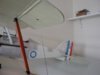
The ailerons need to be joined by a length of thin piano wire, at this scale “quick links” are a non-starter mainly because of their size but in any case there are no detachable linkages on the full size Se5a. Therefore the upper and lower wings will be permanently fixed together by the interplane struts and the aileron linkage; I don’t haven’t enough room to be able to keep the model permanently rigged so this could cause a problem for storing the wings when removed from the fuselage.


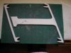
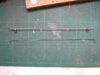
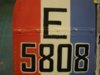
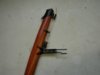
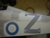
I’ve made 2 frames to support the inner sections of the wings; they are in 2 parts and held together with removable pins.


View attachment 263036


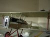
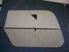
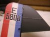
The wings will be stored “hung” from brackets by the top wing, the lower wing supported by the interplane struts and the frame, which grips the trailing and leading edges.


View attachment 263037


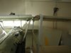
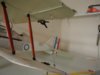
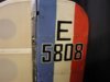
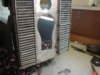
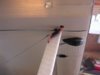
To assemble the model the wing locating pins are pushed a little way into the holes in the centre section and wing stubs, which then take over the support of the wings.


View attachment 263038


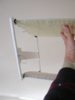
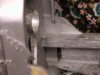
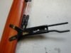
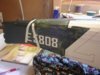
The pin is then removed and the frame disassembled, the aileron controls connected and the wings finally pushed home and the wing retaining grub screws tightened.


View attachment 263039


That’s the theory anyway!
 

Attachments

  • wing frame 1.jpg
    wing frame 1.jpg
    2.3 KB · Views: 0
  • wing frame 4.jpg
    wing frame 4.jpg
    2.3 KB · Views: 0
  • wing frame 3.jpg
    wing frame 3.jpg
    2 KB · Views: 0
  • wing frame 2.jpg
    wing frame 2.jpg
    1.6 KB · Views: 0
This is one of those rare models that really does deserve the description of "Museum Standard". She is looking superb Grahame and I can't wait to see a couple of shots of her in the air.
 
Thread owner
I’m still searching for things to do whilst waiting for the paint to arrive; I hadn’t intended to do this job until much later in the build but needs must etc.


The piano wire, which links the ailerons, has to be the correct length to ensure the ailerons themselves are at the same angle relative to the main planes. Although they are drawn on the plan I prefer not to rely on these but to make them to fit the actual model; a build-up of tolerances (euphemism for building errors!!) can result in the drawings and model not exactly matching, so first I made an adjustable link.


The landing wires are attached to ensure the correct dihedral angle, the ailerons held at neutral with spring clamps and the link adjusted to the correct length.


View attachment 263040


The adjustable link is made from a couple of bent pins soldered to some brass screw clamps from my “useful items” box and a length of 2mm rod. Once locked at the correct length the aileron clamps are released, the link removed and a piano wire link bent to the same length.


View attachment 263041


Fitted in place the link looks a lot better than a 2mm rod attached to control horns by quick links.


View attachment 263042


When the links are permanently fitted the hole in the Solartex will be covered using a frayed tape with a slot in it, but this will be about the very last thing to do to the model, it won’t be done until all the painting etc has been completed and the wings are joined as a single unit.
 

Attachments

  • aileron linkage 8.jpg
    aileron linkage 8.jpg
    1.8 KB · Views: 0
  • aileron linkage 7.jpg
    aileron linkage 7.jpg
    1.9 KB · Views: 0
  • aileron linkage 6.jpg
    aileron linkage 6.jpg
    2.1 KB · Views: 0
looks beautiful grahame learned a lot of nice tricks will help me with my totally scratch built 3rd scale Bristol Fighter. Thanks for such an informative thread. my website is http://www.proflooney.net I will be starting the bristol build in a couple weeks but in the design section I been doing a detailed design thread. on my site is also one for my 1/3 scale gotha V Bomber I am designing and about to start too it has a mere 26 ft ws and i already started using several tips I learned from you to flesh out certain areas of both planes I was figuring out how to do them well.

Joe
 
Joe,

Good to see you here as well. How are the Bristol and Gotha coming along?

James.
 
Hi James they going good waiting on parts for both and trying to get ahold of the flair nose section former drawings and the nose section plans for the bristol as I like the nose on it very scale outline and that should finish up the bristol design for the most part. thats the area giving me fits trying to get right.
 
Thread owner
I always use silver Solarlac to fuel proof the engine bay; firstly because you can see where you’ve been and more importantly where you’ve missed and also because it shows up any places where the joints are less than perfect and believe me there’s quite a few of them!


View attachment 263043


You can see where the corner of the engine bearer meets the former there is a slight gap; it’s not a strength issue at the moment but the crevice could hold fuel / oil and eventually it would soak into the wood and cause problems. I’ll fill it and any others with epoxy / micro balloons then give it another coat of Solarlac.
 

Attachments

  • engine 3.jpg
    engine 3.jpg
    2.4 KB · Views: 0
what are these "micro balloons" you talk of?

....im guessing they are tinny little ballons lol but any technical info/pics/discription and how/what they are used for would be great!
 
Thread owner
Richard

Although the grammar doesn’t sound good I think the best description would be that micro balloons is a very fine powder; whether or not each grain is in fact a hollow sphere I’ve no idea but it is very light though not “spongy” like polystyrene. It is used to “bulk out” glues, typically epoxy; it becomes more capable of gap filling as it makes the glue into a stiffer mix without adding too much weight. I’ve also used it to “mould” simple shapes by mixing enough micro balloons with epoxy to make a very stiff mix, waiting until the epoxy is starting to cure and then forming the shape with my fingers; a final sand once fully cured finishes the job.

Grahame
 
yes grahames correct. basically microballons is kind of a thickening agent which helps the epoxy hold shape. it is commonly used to create fairins etc. other agents that work similar are talc and cabosil.
 
Thread owner
How much “weathering” is appropriate, if any at all, is a matter of personal preference; I like my models to look as if they’ve seen a fair amount of action, others like a pristine, ex-works finish. Also you can see that the lettering looks obviously hand painted, as it should do for a WW1 aircraft; accurate, computer generated transfers just wouldn’t look right.


View attachment 263044


Some of my comments during this thread such as “ I don’t worry about the odd scratch or dent” may have given the impression that a “weathered” finish is an easy option, I can assure you that it isn’t! To get the correct amount of wear and /or damage in the correct places so as to make the model look “real” is a work of art in itself. Some scratches and dents can be left; others can’t and have to be repaired.
 

Attachments

  • weather1.JPG
    weather1.JPG
    2.8 KB · Views: 0
\ said:
“ I don’t worry about the odd scratch or dent” may have given the impression that a “weathered” finish is an easy option, I can assure you that it isn’t!
That is very very true, espeacially at AFV models. Some people say that when you build a tank as an example, you can get it really wrong, and you can still make it look acurrate. The heavy weathering might mask many mistakes, but that isn't a reason to make it look more "dirty".

To get the correct amount of wear and /or damage in the correct places so as to make the model look “real” is a work of art in itself. Some scratches and dents can be left; others can’t and have to be repaired
I also agree with this. At a World War I plane there is a lot of friction. For an acurrate plane you surely have to work a lot at weathering. Some people like their models to be "clean"... it's ok, but they have nothing special, unique, and that's the part where you show your skill.

Great job! I admire your work.:bravo:
 
Thread owner
Although WW1 aircraft were not spray-painted, one substance certainly was liberally sprayed about and that was oil! This is where things can go horribly wrong; having spent a fair amount of time painting the model it needs to be “dirtied up”, paying special attention to any white areas. An error now and it’s a re-painting job.


Ideally I’d have finished all the painting before I started on this stage but as I’m still waiting for the PC10 I’ve made a start where I can. Here’s the rudder after this second stage of weathering.


View attachment 263045


I apply the paint, which is very watered down, with a rag and wipe it in the direction of the airflow slowly building up the “dirt” to what I consider to be an appropriate amount.


The under surfaces of the tail plane really get the treatment, as will the under surfaces of the fuselage and the lower wings.


View attachment 263046


It is impossible, because of the lack of quality of photographs from the time, to be sure just how weathered / dirty these aircraft became in service but it is clear that the fields got quite muddy so I think it’s a fair bet that the aircraft themselves got equally dirty.
 

Attachments

  • weather 3.jpg
    weather 3.jpg
    1.9 KB · Views: 0
  • weather 2.jpg
    weather 2.jpg
    2.1 KB · Views: 0
i have to say grahame that looks unbelievable! it looks perfect and exactly to scale (the weathering i mean) if i didnt know better and ignored the unpainted part, i would think i was looking at a photo of the real plane in colour!!

lovely job i cant wait to see the other finished sections!
 
Thread owner
The pitot head is fitted to the R.H. interplane strut; the 2 copper “pipes”, which disappear through a hole in the covering into the wing, are made from twin and earth house wiring, the “hoses” are short lengths of the neutral sleeving. A few years ago I did some wiring work in the house and had the forethought to keep some of the old wire, which used red and black sleeving, the cable available now uses blue and brown.


View attachment 263047


I didn’t want the pitot head attached to the interplane strut too solidly so that a knock might damage the strut, therefore, I used1.5mm diameter plastic rod. I drilled shallow holes in the strut, pushed the rod through the mounting lug into the hole and applied a drop of thin cyano before trimming the rod over length. A touch with a sanding disc “mushroomed” the end producing a realistic attachment and twists of wire for hose clips finished the job.


View attachment 263048


Obviously it still needs to be weathered, talking of which, it may sound bizarre but the “dirt” on the underside of the tail plane in the post above is at the moment too clean, it will all be blended in at a later stage by gently rubbing over with a pan scourer.
 

Attachments

  • pitot 3.jpg
    pitot 3.jpg
    2.2 KB · Views: 0
  • pitot 2.jpg
    pitot 2.jpg
    1.5 KB · Views: 0
Well Grahame,

I've just finished reading your thread up to this point and I must say you've done a magnificent job. I've learned alot from this build and I look forward to seeing you complete it.

Scott
 
Thread owner
I’ve just looked back through the last few pages to find out how long it’s been since I ordered the PC10 and it turns out to be just over 2 months. The reason for this is that the “new” PC10 (dark) arrived over the weekend but according to Phil at Fighteraces he’d been sent the old PC10. On further checking with the manufacturers in America it was discovered that this was indeed the PC10 (dark) but it’s nothing like the colour shown on the website and is in fact very similar to the old PC10.


The website has been updated in the last few days to show this colour but it’s definitely not what I want for my SE5a so that’s a couple of months wasted. I emailed Chuck Graves of Warbird Colors about this and he pointed me in the direction of some German WW2 colours that are a very close match to the colour I want,


As I’ve said before the colour of PC10 is at best an educated guess and as I’m not a competition man I’ve decided that Schwarzgrun RML70 is near enough for me.


View attachment 263051


The paint has had some talcum powder added to produce a nice matt finish and obviously still needs to be weathered but I think it looks a lot better than the lighter shades.
 

Attachments

  • painting 11.jpg
    painting 11.jpg
    2.4 KB · Views: 0
Thread owner
The templates for the white lettering are what I call “positive”; that is they are the actual shapes, which I draw around, not holes cut out. Here a card “Z” is held in position on the fuselage side with low tack masking tape.


View attachment 263052


I don’t know about you, but I find painting rather boring, not weathering, which I enjoy, as it really brings the model to life and makes it an individual “miniature aircraft” as opposed to a model. It’s the slapping on of the overall basic colour that really drags, especially with the prospect of having to apply 3 or 4 coats around a fairly complex shape as below.


View attachment 263053


There are a couple of things I do to relieve the boredom and a couple of things I don’t do. The photo above shows one of each! I do, if practical, split the painting into smaller sections. The section behind the rear white stripe has had 2 coats and the rear edge of the “Z” made a convenient place to stop the next section, the first coat will be continued forward before applying the second coat and so on. I don’t use a thick coat of paint to reduce the number of coats required, it may indeed reduce the number of coats of paint but the chances are that you’ll end up spending a lot of time and effort trying to remove sags and runs from the paint and the finish will never be as good as a build up of thin coats. You can tell from the area with only one coat that the paint is quite thin, it hasn’t covered very well but the second coat is a great improvement. Another thing I don’t do is rush the job; I always allow ample time for one coat to dry completely, not just “touch dry”, before applying the next.


Another thing I try to do to alleviate the boredom is to take breaks from painting and do a bit of detailing. Unfortunately I have done most of the small detailing work whilst waiting the 2 months for the paint to arrive, but there have been a couple of things to make.


The control for the radiator slats. It doesn’t show up very well, I’ll take another photo after the front has been painted.


View attachment 263054


The tubes from the pitot head exit the wing at the root and are encased in the rear of the cabane strut.


View attachment 263055


The other hole in the covering is for access to the aileron control cable adjustment and will be patched once they are set up correctly.
 

Attachments

  • rad slat 13.jpg
    rad slat 13.jpg
    2.7 KB · Views: 0
  • painting 13.jpg
    painting 13.jpg
    3 KB · Views: 0
  • painting 12.jpg
    painting 12.jpg
    2 KB · Views: 0
  • pitot4 (.jpg
    pitot4 (.jpg
    1.9 KB · Views: 0
Status
Not open for further replies.
Back
Top