Theme editor

Scale Model Shop

SE5a CONSTRUCTION BEGINNING TO . . .

Status
Not open for further replies.
Thread owner
I had the comment made to me that it was a pity to “spoil” the covering by having to use patches. Well just have a look at this photo of the Shuttleworth SE5a.


View attachment 263056


This is an aircraft that doesn’t fly that often, is lovingly maintained and certainly doesn’t have to take the sort of punishment handed out on a WW1 airfield.
 

Attachments

  • patches (2014_01_28 14_36_24 UTC) (2015_09_17 17_13_18 UTC).jpg
    patches (2014_01_28 14_36_24 UTC) (2015_09_17 17_13_18 UTC).jpg
    1.8 KB · Views: 0
It continues to be a breathtaking model Grahame, I am completely with you on the weathering. I try to make a model look like a reduced version of the real thing so I strive to make it look as realistic as possible by careful weathering, which, like you, I really enjoy doing.
 
The inspection patches were instigated by the CAA several years ago,like the De Havilland Tiger Moth's in service today the CAA stipulated that over 100 doped inspection patches needed to applied at strategic points along the wings,these serve to keep a constant check on internal structure integrity,inspection of the control runs and general condition,this scenerio was started when a former crop spraying Tiger Moth broke up in flight during aerobatics in Australia,that particular aircraft had been subjected to agricultural chemicals that affected the integrity of the airframe,and so as always happens everyone owning old biplanes has suffered since.

Standard S.E.5A aircraft in service during WW.1 were considered expendable,and as such had very little airframe inspections,most did not last that long anyway ? as such their wings were just patched us as required,but they did not have set inspection patches like the Shuttleworth example which has to meet modern airworthiness requirements.
 
Thread owner
Thanks for that info Barry, another insight into the history of the SE5a. I’d assumed that the patches must be for some sort of inspection because of their regularity; of course the Shuttleworth example is subject to modern day peacetime airworthiness regulations, a lot more rigorous than WW1 requirements!

The point I was trying to make was that patches on fabric-covered airframes are / were very common and don’t in fact “spoil” the covering. Of course I don’t know how many or where any patches may have been at any given time on SE5a E5808, but then again nor does anyone else so they can’t say it’s wrong.
 
A bit more information on fabric aircraft patches,they are called 'Woods frames' these consist of a celluloid disc or square disc,to use you merely dope the frame straight onto the fabric,allow to dry then with a knife cut into the frame leaving the inspection hole,then a doped piece of fabric is placed over the hole with suitable overlap,on inspection the fabric is ripped off,the inspector then uses a small mirror and torch to look internally and sign the work off,then new patches are applied,and hopefully the paintwork touched up,usually it looks a bit untidy as you never get a perfect match,but anyway for anyone wondering what they are all about that is the way it works
 
Thread owner
The painting of the fuselage is now finished; the individual pieces were painted separately then fitted in place ready for weathering, this will ensure that the weathering “flows” from panel to panel in a natural way.


View attachment 263057


I need to leave it for a while to let the paint really harden off before I start wearing it away with a pan scourerer, that’ll really show up the rivets and panel edges etc. Only when I’m happy with that stage will I start to “dirty” it up a bit.


Here’s a better shot of the control rod for the radiator slats.


View attachment 263058


There’s lots of “damage” to the lower part of the front panel, which will eventually be very heavily weathered with chipped and worn paint.
 

Attachments

  • rad slat 14.jpg
    rad slat 14.jpg
    3.2 KB · Views: 0
  • painting 14.jpg
    painting 14.jpg
    3.1 KB · Views: 0
Thread owner
“Dirtying up” the fuselage has been a bit of a hit and miss affair; with the PC10 being very dark it’s hard to tell where the very thin black paint has been applied and how much it may have built up in places, until it’s actually dry that is and by then of course it’s too late to do any corrective work if there’s too much build up of paint.


View attachment 263059


The finished effect needs to be quite subtle and I’m not happy with the front section, that is in front of the oil cover, so this area will be repainted with PC10 and the process repeated. The other side has worked out OK.


View attachment 263061


As far as the wings and tail plane are concerned the parts to concentrate on are the areas behind the hinges and the leading edges, but once again the effect is quite subtle. The colour of the paint in the photos varies depending on how the light falls on it, but this is not as noticeable in “real life”.


View attachment 263060


The roundels on the top wings also need careful attention; the stitching really picks up the “dirt” and the area behind the hinge, which is hidden by the aileron gap cover, shows up a lot more than on the PC10.


View attachment 263062


I can assure you that the roundels are round; it’s just the way it looks in the photo!


Another photo showing how the dirt picks out the stitching.


View attachment 263063
 

Attachments

  • painting 19.jpg
    painting 19.jpg
    2.2 KB · Views: 0
  • painting 18.jpg
    painting 18.jpg
    1.9 KB · Views: 0
  • painting 17.jpg
    painting 17.jpg
    2.3 KB · Views: 0
  • painting 16.jpg
    painting 16.jpg
    1.6 KB · Views: 0
  • painting 15.jpg
    painting 15.jpg
    2.8 KB · Views: 0
A really nice sympathetic weathering job Grahame. Beautifully done and combined with your attention to detail and the use of appropriate materials is going to make for a model that is going to be as near to a perfrect miniature replica as you are ever likely to see.

Seeing the landing struts in your latest shots reminds me of the first few shots you took when you first started this model and how it has now all started to really come together.
 
Grahame can I ask another silly question about the colour of your plane as it looks very dark I thought WW1 aircraft where brightly coloured or did that change as the war progressed or where the bright schemes propaganda

AMAZING work mate
 
Thread owner
Richard, it seems a long time ago that I was working on producing a nicely stained undercarriage and to some it may seem like sacrilege, but this is what it looks like now!


View attachment 263064


As for the colours, it was really the Germans who went for the “flashy” paint schemes and very nice models they make too, perhaps the British were / are too reserved. In the photo of the Shuttleworth SE5a you can see how dark the PC10 is, this is a latter variation, some of the earlier ones were a lot lighter, but whatever base colour was used the red wheel covers are about as far as they usually went, although there are one or two examples of fairly bright “nose art”.


Of course as I’ve said on several occasions, PC10 was not a colour as such; it was the 10th variation of Protective Coating and consisted of several layers of clear dope, undercoats, etc., etc.
 

Attachments

  • painting 20.jpg
    painting 20.jpg
    2.7 KB · Views: 0
Grahame,

I can only repeat what I have said before, this is a truly awesome model, even more so now she is gaining her colours, the weathering so far looks fantastic. I trust this one will be doing the rounds at the shows in the new year because I can see her reaping in the awards.

Keep the pics coming

Regards.....Mark
 
Thread owner
Mark


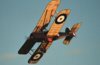
The only show where I’ll display the model will be my club's annual air show, which is the Teesside Model Flying Club, near Stockton upon Tees. If any one's up this way in June I can thoroughly recommend it as an excellent day out.


Grahame


I’ve repainted and weathered the offending front section of the fuselage and am now happy with it.


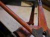
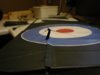
The elevators are actually operated by a pair of pushrods but I want it to look as if the scale control cables and pulleys control them. To do this I will run a cable from the top control horn on one side to the bottom control horn on the other and vice versa; to take up any slack I will include springs in each cable run.


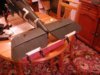
The first thing to do is to find out where any slack in the system may be by temporarily joining the elevators together and connecting the control horns with cotton. I did each cable separately to ensure there wasn't any interaction.


View attachment 263065


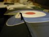
Moving the elevators from full up to full down showed that there is in fact no noticeable slackening or tightening of the cables; more by luck than judgement I’m sure! I’ll still incorporate the springs but with just enough tension to stop the cables flapping about


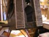
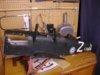
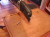
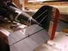
I made up the 2 cables complete with springs; as they won’t be seen I used the easy option of brass tube as crimps, with a drop of cyano just to be sure.


View attachment 263066


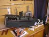
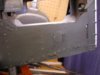
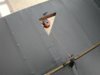
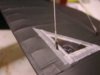
I fitted the cables through the fuselage before threading them through the tubes built into the tail plane, one spring each side.


View attachment 263068


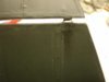
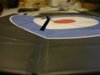
I then attached the cables to the control horns ensuring that there was equal tension in each cable by the simple measure of ensuring that each elevator was at the same relative angle. There is a little friction introduced by the pulleys and the springs running inside the tubes but definitely not excessive, as I’m using a separate servo for each elevator I’m certain there’ll be no problems.


Just the acetate “windows” and frayed tapes to fit now.


View attachment 263067
 

Attachments

  • elevator control 10.jpg
    elevator control 10.jpg
    2.5 KB · Views: 0
  • elevator control 11.jpg
    elevator control 11.jpg
    1.6 KB · Views: 0
  • elevator control 9.jpg
    elevator control 9.jpg
    1.5 KB · Views: 0
  • elevator control 8.jpg
    elevator control 8.jpg
    3.3 KB · Views: 0
Thread owner
Apparently when I said in my last post “ensuring that there was equal tension in each cable by the simple measure of ensuring that each elevator was at the same relative angle” it didn’t mean much; I knew what I was talking about but of course I’d done it! Rather than just explaining the tensioning bit I thought I might as well do a step-by-step account of the elevator set up. If you’re building an SE5a, or similar and want to incorporate the pulleys etc., or you’re a bit “nerdy” like me and like reading technical stuff then the next few paragraphs may be worth reading. Then again you might just be suffering from insomnia and what boring to sleep!

The cables each consist of a spring with “tails” attached to both ends. A short “tail” that is attached to the control horn on the same side as the spring, which I’ll call the sprung cable. A long “tail” that passes through the fuselage and attaches to the other control horn; I’ll call this the non-sprung cable although of course the spring does have exactly the same effect on it.

My original idea was to pass the non-sprung cable through the centre of the spring of the other cable but in practice this wasn’t a good idea. When some tension was applied to the spring and the coils opened slightly the non-sprung cable could get between the coils and this caused a lot of friction; running the cable on the outside of the spring, between it and the tube in the tail plane, caused no problems.

I threaded the cables through the 2 halves of the tail plane bringing the sprung cables out for the top control horns and the non-sprung cables out for the bottom control horns. The choice was purely arbitrary but if done the other way round the following steps would have to be reversed.

The model was turned upside down and the non-sprung cable pulled until the spring hit the fuselage side. With full up elevator (remember the model is upside down) I bent the cable back on itself ¼" past where it met the control horn thus ensuring that in practice the spring would never hit the fuselage side. The cable was threaded through the control horn and fixed by binding with thin copper wire and a drop of cyano. This was then repeated for the other side.

The model was then turned the right way up and the elevators temporarily joined by a length of spruce and clamps. One of the sprung cables was threaded through its control horn and pulled until there was sufficient tension to keep the cable tight and provide enough friction on the pulleys to make them rotate when the elevator was moved from full up to full down. This turned out to also be about ¼" but I tensioned it just that bit more to be on the safe side and then terminated the cable as before.

When I removed the spruce “joiner” the spring contracted and I had one elevator deflected up and the other deflected down.

Now we get the "equal tension" bit! I threaded the other sprung cable through its control horn and tensioned it until both elevators were in line. When operating the elevators together there’s no pulling against the springs as the tension of one counteracts the tension from the other.
 
Thread owner
I used canopy glue to attach the acetate “windows” and then added the frayed tapes. They’ll be painted once the inspection “windows” in the wings and the aileron connecting wires are in place and taped.


View attachment 263072


I’ve bolted the fin to the fuselage and added the tail plane support wires; they should be solid wires but I decided to use fishing trace because it would make life easier if / when I have to alter the incidence of the tail plane. I don’t know what it is but they just don’t look right, so much so that they’ll have to be changed, if it means more trouble later on I’ll just have to live with it; I think I’ll get some 24swg piano wire and hope that looks better.


View attachment 263073
 

Attachments

  • tail 9.jpg
    tail 9.jpg
    3 KB · Views: 0
  • tail 10.jpg
    tail 10.jpg
    2.2 KB · Views: 0
The se5a looks absolutely stunning. It's been great to watch the build progress and it's really apparent how much effort and attention to detail has gone into this build.

I remember seeing the initial posts showing the images of those inspection windows on the actual aircraft - the model really does look the part and has really come alive now.
 
Grahame you have done the subject proud,and what a great record we have of your SE5a thanks to your kindness,how you keep your workbench so clean and tidy after building such a model beats me ?

Cleaning your model after flying will be a task in itself, with all of that beautiful detail to look after.

The elevator cable springs remind me of the longitudinal trimming system for the Tiger Moth, whereby a tension spring gives a false sense of fore and aft movement,the first time that you see it makes you realise how effectivly simple it all is.

And now begs the question ,what are you going to build next ? we will not deny you a well earned rest,but I doubt that you will for one minute even consider it ?
 
Thread owner
The “windows” were virtually the first thing that I considered when starting this model, they have influenced the design and construction throughout and will actually be virtually the last thing to be added to the model. I’ve replaced one of the tail plane support wires with one made from 24swg piano wire and it’s a lot better, the model shop hasn’t got any in stock but fortunately Mike’s putting in an order this week so it should be there some time next week. In the mean time I can get on with the rudder and aileron control cables.

I have already given some thought to my next project; I quite fancy building a twin, either a Vimmy or a Gotha are favourites at the moment. I prefer the Gotha but it has some serious drawbacks, no the least of which is the “pusher” design, which if done conventionally will make for a lot of lead up front to get the CG right. I’m toying with the idea of a “standard” engine mounting at the front of the nacelle with a lay shaft to the prop at the rear, but as I’m a modeller and not an engineer it might be a recipe for disaster. If I go down that route a lot of experimentation will be called for!

Then again I really like the Pfalz DXII: decisions decisions.
 
\ said:
Then again I really like the Pfalz DXII: decisions decisions.
Just thinkwhat a great counterpart the Pfalz DXII would be to the SE5a - and lots of opportunities for some interesting camouflage too - hexagonal camouflage and some vivid fuselage colours too! Can't wait to see it progress - whatever model you choose!
 
Thread owner
It’s been quite a busy week but not a lot to show for it on the modelling front; to start with on Sunday I got my second “badge of office” as an official wrinkly, the first was my bus pass and now I’m a Granddad! Between the cooing I managed to get a bit of time down the shed and threaded the aileron control cables. I’ve tested the top ailerons and they work fine, but of course they’re the easy ones, I’m hoping to test the bottom wings and also connect the top and bottom ailerons tomorrow.


One thing I’m pleased with is the control horns, this is the first time I’ve had them “operational” and I have to say I think they look good.


View attachment 263074


In the neutral position the shackles are inline with the cables.


View attachment 263075


It’s only when the ailerons are deflected that it shows that the shackles aren’t actually free to pivot.


View attachment 263076


Of course the ailerons will be at neutral when the model is being “examined” and if anyone can see the shackles when the model is flying they’re a better man than me!
 

Attachments

  • aileron control horn 5.jpg
    aileron control horn 5.jpg
    2.1 KB · Views: 0
  • aileron control horn 4.jpg
    aileron control horn 4.jpg
    2.1 KB · Views: 0
  • aileron control horn 6.jpg
    aileron control horn 6.jpg
    2.2 KB · Views: 0
Status
Not open for further replies.
Back
Top