Theme editor

Scale Model Shop

SE5a CONSTRUCTION BEGINNING TO . . .

Status
Not open for further replies.
Thread owner
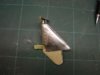
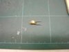
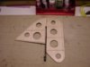
The rudder uses the same method of construction. There’s no separate trailing edge, the core itself does that job; the covering is fastened purely to the edge of the 1/16th core, this works OK because all the edges are eventually taped.


View attachment 262663


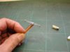
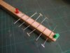
The top and bottom edges have 1/8th x 1/16th balsa added. The balsa is soaked in ammonia for a couple of hours, the pieces for the other side are soaking in the plastic tube, the inner edge is pressed with the back of the scalpel blade to help it bend then it is pinned in place and allowed to dry before gluing.


View attachment 262664


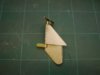
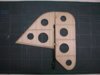
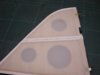
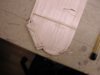
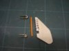
With the lightening holes cut and the edges sanded all that’s left is the hard points for the hinges and that’s another problem.


View attachment 262665


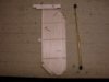
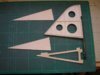
I’ll have to make my own hinges to go around the tail incidence adjuster; I could use a commercial hinge for the top but then they wouldn’t match. If I’ve got to work out how to make one I might as well make them all, including the elevator and aileron hinges, happy days!
 

Attachments

  • rudder 1.JPG
    rudder 1.JPG
    1.5 KB · Views: 0
  • rudder 3.jpg
    rudder 3.jpg
    2 KB · Views: 0
  • rudder 2.JPG
    rudder 2.JPG
    1.9 KB · Views: 0
Without a shadow of doubt this is by far the best type of construction for the tailplane,elevators,fin and rudder,the method is tried and trusted whether working on small scale flying models or large models such as Grahames S.E.5A.

I am not sure that I would have personally bothered to remove those lightening holes as the weight saving is so negligable as related to the extra strength of leaving them untouched,but this is such an individual choice.

The sternpost/rudder hinges will need some thought but I am sure with your ingenuity you will think of a way around it,there is sometimes no easy way out ith these things ? if you are thinking of making the hinges then beware of metal fittings which can cause 'music' and the harmonics cause problems,I have seen models crash because of metal to metal joints,just thought that I would mention it Grahame.
 
so far it looks lovely, keep it up, cant wait to see it when its done!
 
Thread owner
Barry

My philosophy is to save weight wherever possible, but not to compromise strength; I’d rather have a heavy model in one piece than a super light model in a bin bag! I’ve used “core an half ribs”, with holes, on several models and haven’t had a structural failure yet; I hope that’s not going to be a case of “famous last words”.

As for “metal to metal contact” that’s really a misnomer, it’s when metal to metal make and break contact that problems arise. Wheel collets firmly attached to the undercarriage leg cause no problem, but if the grub screws work loose and vibration causes intermittent contact then radio interference could well be the result. If a design calls for say 2 pieces of metal to slide over each other, which might cause problems, one way to over come it is to join the 2 pieces together with a flexible wire that allows the individual movement but ensures there is always electrical contact.
 
The bonding wires are used on full sized aircraft all over the airframe,miss a tree out and see the static build up on the aircrafts radio system,as you rightly say it is chatter between metal that can cause a problem and not metal to metal perhaps I should have phrased that better,not as big a problem as it used to be but still relevant.

I think the core method is perhaps the overall best system for thin surfaces,the advantages being that once built you cannot see the core itself,and once more it is so much easier to construct,I even use a 1/32 core on my small electric models now having proved the system many times.
 
Thread owner
As the build progresses I’m always thinking in advance, sometimes many months in advance, and one thing that has occupied my mind for a while now is whether or not I should make the tailskid steerable. From a purely practical point of view it isn’t necessary as it is only really used whilst taxiing, which for some reason is frowned upon by our club committee; on the take off run the rudder is effective enough on its own. It is also more complicated, with hinges and linkages to organise, not to mention the extra weight, so all things considered I decided against it.


The problem was I was thinking about it “in isolation”; now I’ve come to actually designing the part it is obvious that because of the tail plane incidence adjuster the skid has got to be separate from the front section and will need some substantial fixings, so they might as well be hinges. The best laid plans of mice and men etc.


View attachment 262666


The construction is a variation on the core method; in this case the core is a 1/16th ply frame with tongues to locate it in the fuselage, 1/16th ply doublers at the rear where the hinges will fit and 1/16th balsa sides.
 

Attachments

  • skid 1.jpg
    skid 1.jpg
    2.4 KB · Views: 0
As the build progresses I’m always thinking in advance, sometimes many months in advance, and one thing that has occupied my mind for a while now is whether or not I should make the tailskid steerable. From a purely practical point of view it isn’t necessary as it is only really used whilst taxiing, which for some reason is frowned upon by our club committee; on the take off run the rudder is effective enough on its own. It is also more complicated, with hinges and linkages to organise, not to mention the extra weight, so all things considered I decided against it.The problem was I was thinking about it “in isolation”; now I’ve come to actually designing the part it is obvious that because of the tail plane incidence adjuster the skid has got to be separate from the front section and will need some substantial fixings, so they might as well be hinges. The best laid plans of mice and men etc.


The construction is a variation on the core method; in this case the core is a 1/16th ply frame with tongues to locate it in the fuselage, 1/16th ply doublers at the rear where the hinges will fit and 1/16th balsa sides.
I'm afraid I have to say Greyhead that I would never consider a comittee's preferences when designing or manufacturing a model, I make mine for myself and no-one else.

Let them frown upon what they want, they really need to be putting thier efforts into more constructive pursuits.
 
Here,here,from my past experiences those on the committe at clubs are the less informed on modelling matters and seem more concerned on restricting members than encouragement,they like to make comments to make them feel big because their knowledge is inadequate ! nuf said,we think alike.

Build what you like,how you like and fly it in the manner befitting the real aeroplane and you cannot go wrong.
 
Thread owner
The tailskid is made from 1/8th ply with the hinges from brass tube and strip. To avoid the dreaded “metal to metal contact” the hinge pin is a snake with the outer attached using the time-honoured method of stitching with button thread. The top hinge has a washer soldered to it to act as a bearing


View attachment 262667


Here it is temporarily in position.


View attachment 262668


The tailskid shroud will be from litho plate and will hide the stitching.


With a steerable tailskid there may well some taxiing going on (when there are no committee members about!!)
 

Attachments

  • skid 3.jpg
    skid 3.jpg
    1.6 KB · Views: 0
  • skid 2.jpg
    skid 2.jpg
    1.7 KB · Views: 0
You make good use of the snake material Grahame,it is worth buying just for the alternative uses that it can be put to.

The skid/steerable unit looks very businesslike,there is nothing better than starting the model in the pits and then to taxy out in such a scale fashion,after all you never see a real aeroplane being carried out to the runway,same on landing turn off the strip and taxy back again,but this alone requires the skill to perform it,scale judges love things like this.
 
I completely agree with Barry, I think taxiing in a scale manner is all part of the experience and further enhances your complete operational skills.

Nothing looks more proffesional than seeing the model line up with the runway before starting it's take off run and returning to the pits after a successfull landing.

I guess it wouldn't be able to after an unsuccessfull one!!! :)
 
Thread owner
If you’ve read this thread from the beginning then you’ll know that I have been giving some thought as to how to make the control horns, which are quite thin; with the tailskid being steerable now is the time to put the thoughts into practice.


Thin steel is really the only option for the horn itself but attaching the cable to it is the problem, a standard clevis would be way too big and a cable passing through a hole would quite quickly be worn through. I hope I’ve solved the problem by bending a “yoke” from thin brass rod.


View attachment 262669


A thin brass pin goes through the hole in the horn, it’s peened over at the ends and finally the whole lot is soldered to the horn so that the pin isn’t taking the load. The only problem I can see with this is that the attachment point is slightly in front of the horn but I can get around this but slightly altering the angle of the horn and mounting it slightly to the rear.


The skid has a balsa TE extension and is then shaped with lightweight filler where the litho plate shroud will go.


View attachment 262670


The control is transferred from the horn to the skid via a thin pin to give the servo some “shock protection”, I might also use springs in the cables but from past experience I find these tend to make the steering a bit erratic.


With the shroud fitted that’s the skid virtually finished.


View attachment 262671
 

Attachments

  • skid 6.jpg
    skid 6.jpg
    1.6 KB · Views: 0
  • skid 5.jpg
    skid 5.jpg
    1.5 KB · Views: 0
  • skid 4.jpg
    skid 4.jpg
    2 KB · Views: 0
Grahame have you seen those 1/32 split pins that Nexus supply in packets ? they come in very handy for closed loop systems and jobs like this.
 
A degree of protection can be offerred to the servo by incorporating a 'Z' in to the linkage without loosing too much control and it of course allows a degree of adjustment of the linkage length.

Possibly a bit more reliable than a spring link.
 
Thread owner
Barry

I’ve used small split pins before for the pulley shackles for example; they weren’t suitable for this job as they would have to be bent “the wrong way” around the pin and putting a twist in the legs made them too long, but I may use them for the rudder control horn because that has 2 cables attached both sides.

Richard

All the controls are operated by cables and so far I’ve failed in my attempts to bend them into a “Z”!!

Being serious that’s a really good idea; I could insert a short length of thin piano wire with a “Z bend” into the cable runs, probably use it as a connector to the servo arm, thanks for that idea.

Grahame
 
Thread owner
The hinge is a short length of brass tube soldered to a brass strip, which goes around the tube as a safety measure in case the solder joint fails. The pin is 22 swg piano wire and will have a brass “keeper” soldered behind the rudder LE when in position.


View attachment 262672


The rudder is recessed to allow the hinge line to be central to the radius of the LE which has additional strengtheners added.


View attachment 262673


The brass strip will be riveted to the fin TE either using brass tube or rod, I’ve not decided which as yet, I’ll be doing some experimenting tomorrow.
 

Attachments

  • hinge 2.jpg
    hinge 2.jpg
    2.2 KB · Views: 0
  • hinge 1.jpg
    hinge 1.jpg
    1.6 KB · Views: 0
Those hinges are not going to come adrift in any hurry Grahame,I oonce lost the rudder on my Parnall Elf at Old Warden in flight,the model came down flat with the rudder hanging,a few feet above the ground the model recovered just buckling the undercarriage,it was a very lucky escape as the hinge had fatigued with vibration,you can never be too careful with things like this.
 
Thread owner
The hinges are riveted to the fin TE using brass tube, given a final drop of cyano to securely lock them in place then faired in with some 1/32nd balsa.


As I explained earlier, at this scale “true” rib stitching doesn’t look as good as simulated in my opinion; for the wings I used a compromise which holds the covering to the under camber but looks OK but I can’t use this method for the fin and rudder because of the thin section and the core method of construction.


To simulate the rib stitching a simple jig makes life a lot easier. The thread, I’ve used brown here to show up, is laced around the pins, which are set to the correct spacing, and over the top of the Solatex; to hold them in place I use a tiny drop of thin cyano then give the whole lot a coat of Clearcoat.


View attachment 262674


Thin strips are cut and tacked in position over the ribs and when the top frayed rib tape is ironed on it bonds everything together. The finished rib tape looks near enough like the real thing for me!


View attachment 262675


I should have been more careful with the heat gun when shrinking the LE tape around the top of the fin because the covering has pulled back from the TE, but it doesn’t really matter as there will eventually be a litho plate cover running down the length of the TE.
 

Attachments

  • fin 5.jpg
    fin 5.jpg
    2.2 KB · Views: 0
  • fin 6.jpg
    fin 6.jpg
    1.7 KB · Views: 0
You should see some of the WW1 British aircraft Grahame,quite common to have S.E.5A's with stretched sagging fabric aft of the cockpit area,what they used to do was lace up the underside as a bag with leaded cleats,they used cord drawn through beeswax which takes cellulose dope,so the fabric was replaced in its disturbed state annd sometimes looked a right mess,so I would not worry too much about a few fin wrinkles,as ever aircraft on the front were short lived,if they did not tip onto their noses with novice pilots they would be quickly written off in spinning accidents.
 
I think 'perfection' with such coverings would actually not look as realistic.

I don't know what your thoughts on weathering this model are but the odd crease in the fabric to me will make it look more like, well 'fabric'!
 
Status
Not open for further replies.
Back
Top