I quite agree with your comments on “perfection”, in fact I deliberately introduce the odd scratch and / or dent on my models but what’s happened here is that I let the heat work too much on the covering whilst shrinking the edge tape. Luckily the TE is fairly wide so there’s still enough contact to hold the covering and it will eventually be covered.

You are using an out of date browser. It may not display this or other websites correctly.
You should upgrade or use an alternative browser.
You should upgrade or use an alternative browser.
SE5a CONSTRUCTION BEGINNING TO . . .
- Thread starter Greyhead
- Start date
- Status
- Not open for further replies.
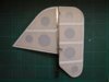
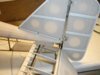
When finishing the fin / rudder assembly I turned up the heat on the iron to shrink the edge tape around the curves, with the covering only attached to the 1/16th edge of the rudder I couldn’t afford any shrink back as happened on the fin. The litho plate shroud conveniently covers that fault and really finishes it off; the hinges and incidence adjuster now look the part.
View attachment 262676
Incidentally the tapes on the rudder are in fact parallel, for some reason they just look that way on the photo.
View attachment 262676
Incidentally the tapes on the rudder are in fact parallel, for some reason they just look that way on the photo.
Attachments
Yes you get that distortion sometimes when doing close up work Grahame,the lens tends to show up the convex nature more.
This is one of the most detailed tail fin/rudder assemblies that I have seen in a long time.
That strip really sets things off.
This is one of the most detailed tail fin/rudder assemblies that I have seen in a long time.
That strip really sets things off.
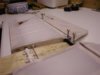
The tail plane presents several problems, not the least of which is how to operate the elevators. I prefer to use the same method as the full size aircraft even if this is quite complex, as with the Elf; in that case the linkages were external so easy to check and maintain, but I have reluctantly decided that using the scale closed loop system is not practical for the SE5a tail plane, I still intend to use it for the ailerons. With the rear of the fuselage being open I should be able to hide the non-scale linkage.
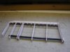
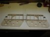
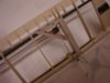
The main spar, made from 4mm carbon fibre tube, will have a piano wire pin into the fuselage held by a grub screw similar to the wing fixing; it also acts as a pivot point for the variable incidence. I’ve also used a carbon fibre tube for the TE; this is short because the tail plane tapers towards the tip.
View attachment 262677
The ribs are cut long so there is sufficient strength around the hole for the carbon fibre TE during construction and are trimmed back later for the addition of a 1/64th ply facing.
Here’s a photo of one half, complete with piano wire pin, ready for the hinges and bracing wire hard points.
View attachment 218869
The tail is 2 separate units so I’ll connect them with a short length of carbon fibre slid into each TE to ensure that any adjustment to the incidence is equal both sides.
View attachment 218870
Attachments
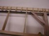
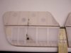
I’ve used the simple but effective core method for the elevators. With hindsight I shouldn’t have cut the lightening holes in the 2 outer bays; because the tail plane tapers down to just 1/16" at the tips there is very little strength left.
View attachment 262679
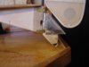
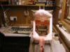
I’ve added some carbon fibre tows, which help. The carbon fibre TE joiner is only glued on one side to allow the 2 piano wire pins to slide into hard wood blocks in the fuselage, which are then held in position by 2 bolts tightened through holes in the bottom. If I can find a 0.9mm Allen key long enough I’ll replace the bolts with grub screws; I might have a go at extending the one I’ve already got.
View attachment 262680
The photo is blurred where it matters; the camera insisted on focussing on the very rear of the fuselage and not the blocks!
Finally a photo of the finished tailskid in position.
View attachment 262681
For practicality I’m going to bolt it in position, this will mean that I’ll be able to easily remove the skid, fin / rudder and tail plane halves from the fuselage if it becomes necessary. Once every thing has been thoroughly tested and proven, then I may attach the skid permanently as per full size.
View attachment 262679
I’ve added some carbon fibre tows, which help. The carbon fibre TE joiner is only glued on one side to allow the 2 piano wire pins to slide into hard wood blocks in the fuselage, which are then held in position by 2 bolts tightened through holes in the bottom. If I can find a 0.9mm Allen key long enough I’ll replace the bolts with grub screws; I might have a go at extending the one I’ve already got.
View attachment 262680
The photo is blurred where it matters; the camera insisted on focussing on the very rear of the fuselage and not the blocks!
Finally a photo of the finished tailskid in position.
View attachment 262681
For practicality I’m going to bolt it in position, this will mean that I’ll be able to easily remove the skid, fin / rudder and tail plane halves from the fuselage if it becomes necessary. Once every thing has been thoroughly tested and proven, then I may attach the skid permanently as per full size.
Attachments
G
Guest
Guest
Grahame, just something you may find usefull one day.
Most camera's have a two stage shutter release and the vast majority set focus and exposure on the first stage and then actually open the shutter on the second stage.
In your picture above if you had placed an object next to the subject at the same distance away from the camera as the point you want to focus on, focused on that by pressing half way and then holding the shutter release button at the first stage point. Then simply swing the camera across to your actual subject and press the shutter release button all the way. Holding the button at the first stage holds the focus and exposure settings which can be usefull for just the type of shot you have tried there.
If your camera does not do this then I apologise but I think it was worth mentioning anyway.
G
Guest
Guest
Wow, thats an impressive model. Its amazing reading your construction commentry!
I want more.
Euan
I want more.
Euan
G
Guest
Guest
Definately an improvement and at least the camera is not focused on the end of the tunnel now.RichardThanks for that tip; it’s still not perfect but a lot better and the technique obviously works!
G
Guest
Guest
Hello Grahame,
now that some weeks passed since you last read a message from me I really have to post here in your SE5a development thread. It's great to see the plane get better from day to day. Most pleasure for me is that you don't lock your know-how away. It seems that you're doing your best to improve our modeling skills.
Seeing how you lay your interest on details and how you scale them down to an eyecatcher that is looking real is pure joy.
Thank you for that, Grahame.
:respect1:
Dirk.
p.s.: Please greet your brother from me and tell him, that even if he doesn't like to document his project here, I would be very happy about finding some photos in my mailbox") or just some written lines about the kit and the differencies to the original.
or just some written lines about the kit and the differencies to the original.
now that some weeks passed since you last read a message from me I really have to post here in your SE5a development thread. It's great to see the plane get better from day to day. Most pleasure for me is that you don't lock your know-how away. It seems that you're doing your best to improve our modeling skills.
Seeing how you lay your interest on details and how you scale them down to an eyecatcher that is looking real is pure joy.
Thank you for that, Grahame.
:respect1:
Dirk.
p.s.: Please greet your brother from me and tell him, that even if he doesn't like to document his project here, I would be very happy about finding some photos in my mailbox
or just some written lines about the kit and the differencies to the original.I’m only to pleased to pass on any tips that I have, if it encourages more people to advance from ARTFs it’s an effort not wasted! One thing I have learnt in my years of aeromodelling is that you never stop learning; every new model presents new challenges.
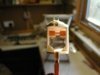
I’m not sure whether this is the third or fourth version of the control pulleys but they are now at a stage of development that I feel warrants a trial. The problems that have arisen during tests have been the pulley wheel jamming and the cable jumping out of the groove in the wheel if there was any slack in the system.
Here is a photo of the new components and a finished assembly.
View attachment 262684
The jamming has been cured by using a larger diameter bush in the wheel and an extra length of tube slightly longer than the thickness of the wheel through which the pin goes; this ensures that the wheel doesn’t bind on the shackle when the pin is peened in position. The extra “arms” on the shackle are bent around the edge of the wheel to prevent the cable jumping from the groove.
Attachments
G
Guest
Guest
Hello Grahame,
perhaps it wouls be possible to etch the unrolling of the guiding (you showed us on the photo of the pulley wheel in one of your first postings in this thread) out of copperplate. By soldering that part together you should get rounded edges on the inside of the guiding and a quite exact part which could easily be installed, wouldn't harm the wire (rounded edges on the inside) and which would really serve as an eyecatcher. Last but not least this solution should be exact enough to help you getting rid of the jumping out problem you have.
Greeting from the continent.
Dirk
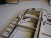
Having made 2 pulley assemblies I decided to trial fit them in one half of the tail plane before making the rest. Fitted temporarily and using button thread for the cables has proved that the pulleys are OK but that my calculations for the height of the elevator horns were wrong; they need to be 2mm taller to prevent the cables catching on the covering support.
View attachment 262685
The final cable runs will all be through the ribs but at this stage it’s just easier to leave them on the outside.
View attachment 262687
I was talking to a friend about the elevator controls and he wondered why I wasn’t going to use the scale system for the elevators, but was for the ailerons, especially as I’d gone to all the trouble of making working pulleys; so here’s the explanation:
The pulleys have to be incorporated anyway because they are a very “visible” part of the model, but the problem is getting the control cables into the fuselage in such a way as to be useable. If I’d designed the tail plane as a one-piece unit it may have been practical but it just wouldn’t look right and making the tail incidence adjustable would then have been impossible without having gaping holes in the side of the fuselage. With the aileron linkage there’s a lot more room and only one cable per side, which can be attached directly to a servo, should be no problem (famous last words!!).
Attachments
The elevator control pulleys work far better now that they have their solid attachments and the tubes for the cable runs. The tubes are free if you’re lucky; they are what lengths of piano wire are in when they are delivered to your local model shop and are usually thrown away.
View attachment 262688
In fact they work so well with the cables connected, at the moment only using button thread, that I’m wondering if it may be possible to actually use them for the elevator control. I’ll get them covered and leave the decision till later; it’ll involve some quite major “surgery” to the rear of the fuselage but if at all possible it will be worth the extra effort.
View attachment 262689
Here’s a photo of the tail plane in position; the elevators have already been covered.
View attachment 262690
I have usually covered my models with white Solatex as I find that any colour paint produces a good solid cover over it, but for the SE5a I’m using natural as the underside is plain, doped linen. When I covered the fin and rudder I used scraps of white Solatex for the rib tapes, but for the elevators I used the same Solatex that I’m using for the main covering and this was when I discovered that it is so much easier the fray the natural Solatex.
If you are building a WW1 model and you’re going to fit rib tapes I strongly suggest that you use natural Solatex even if it’s not the best match for your paint, it really is that much easier!
Attachments
G
Guest
Guest
Wow, thats amazing, down to last little detail!!!
Euan
Euan
My original thoughts on the elevator control were that the 4 cables would have to run forward to a servo, or more probably a “slave” bell crank, just behind the cockpit. This would involve 4 extra pulleys mounted behind the tail plane fixing block, therefore the cables would have to exit the tail plane at least the diameter of the pulleys plus half the thickness of the fixing block behind the pivot point. This in turn means that if the tail plane incidence needed to be changed, almost a certainty, the cables would move through a considerable distance so the pulley fixings would have to be able to accommodate this; all very complicated and therefore most likely unreliable. Not the sort of thing you want in such a vital system so I decided against!
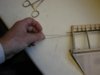
As I took the photos, for the previous post, of the pulleys with the cables in place I held them tight with my finger and thumb; this is when I had a “eureka” moment, if I twisted my finger the elevators moved!
View attachment 262691
My idea now is to use a horizontal drum mounted close behind the fixing block with one cable going from the top horn of one elevator, a complete turn around the drum to the bottom horn of the other elevator; a “slave” cable will join the other horns together to transfer the pull.
That’s the theory anyway; I’ll build a test rig and do some experimenting but I’m not going to cut off the “working” control horns just yet! This is still at the early “thinking” stage so any suggestions will be gratefully received.
Attachments
G
Guest
Guest
coming along nicely greyhead
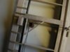
Well having spent a couple of days with the tail plane on a jig experimenting with various pulleys, drums and bell cranks it’s back to plan A!! The problem in the end was not the pulleys etc. but being unable to get the correct and equal tension in all the cables. The aileron controls will have an adjustable “quick link” where each wing joins the centre sections but with the tail plane there just isn’t the space.
The elevators will actually be moved via a snake and ball link, which will be pretty much hidden inside the rear of the fuselage.
The cables go straight from one side of the tail plane to the other and are for “effect” only but look quite convincing; these photos show the final trial set up on the jig.
View attachment 262693
View attachment 262696
Attachments
I’m not surprised that you had such problems trying to use the pulley system in what was essentially a closed loop system, unless I’ve misunderstood you. Closed loop systems seem simple on the face of it but to get just a straight forward servo to rudder system working where one wire doesn’t go slack can be a challenge and there is a lot of geometry involved not to mention the Ackerman effect.
Anyone wishing to read further on the subject of designing closed loop systems could do worse than to read this excellent on-line article by Brian D. Felice at http://members.cox.net/bdfelice/Ackerman/ackerman.htm, he has a lot of other useful articles on his website as well.
The SE5 is coming along fine Grahame and I'm hoping to try a instrument panel along the lines of yours in my Auster J1.
There is a lot of scale effects coming into play here,take a study of a Tiger Moth control system next time you see one,cables flapping around and twanging against the fuselage fabric,it is all about tension and adjustment,sadly when working to such a small scale things get exagerated and slop becomes a real issue,and dont forget that most full sized machines have balance cables,these ensure that there is adequate tension on the control system,and there is another important difference between full sized and model,whereby our models rely on a fixed servo to operate the controls via cables there is no balanced aerodynamic effect to take the load away from the power source ie servo,full sized controls literally 'fly' and are assisted with mass balances to make the aircraft more pleasant to handle.
So this is one area that is heavily dictated by the sheer small scale down effect,it cannot be emulated exactly the same as its real counterpart,so we have to compromise.
So this is one area that is heavily dictated by the sheer small scale down effect,it cannot be emulated exactly the same as its real counterpart,so we have to compromise.
- Status
- Not open for further replies.
Legal Notice
scalemodelling.co.uk is a privately operated online discussion forum. All content posted by members reflects their own views and opinions and does not necessarily represent those of the forum owners or administrators. While reasonable efforts are made to moderate content, no responsibility is accepted for user-generated material. By using this site, you agree to comply with UK law and the forum rules.