Theme editor

Scale Model Shop

SE5a CONSTRUCTION BEGINNING TO . . .

Status
Not open for further replies.
Grahame always take great care when using Paxolin,I lost a wormate who breathed in the dust which poisoned his system,so whatever you do take precautions.

A suitable safer alternative is layered sheets of domestic work surface.
 
Thread owner
Paxolin has a degree of flexibility whereas Formica type laminates are quite brittle but as is often the case the perfect material for a particular job has some health and safety issues, in this case quite serious ones; that is why it’s no longer available from your local model shop and has to be bought "trade".

I always wear a dust mask when cutting or sanding Paxolin and if possible do it outdoors; the same goes for sanding balsa and plywood but to a lesser degree.
 
Thread owner
I’ve not yet decided on the best method for making / attaching the cowl. The engine cylinder heads project through both sides so the alternatives are to make one unit complete with cylinder heads or individual sides with the cylinder heads attached and a separate top; both methods have their pros and cons but as the starting point is the same for both, the decision can be put off till later.


The initial framework is constructed using the fuselage as the “template” to ensure accuracy.


View attachment 262748


At this stage the framework is quite flexible so it is firmly wedged in position before the 1/16th balsa skin, which will give it its rigidity, is added.


View attachment 262749


The rear of the cowl buts up closely to “F2” and what cannot be seen in the above photo is the cling film used to stop the rear former being inadvertently glued to it. The front former is set back because the final litho plate skin will have slots to clear the cabane bracing wires and fuel pipe so the cowl will have to be slid back into position.
 

Attachments

  • cowl 1.JPG
    cowl 1.JPG
    2.2 KB · Views: 0
  • cowl 2.JPG
    cowl 2.JPG
    2.3 KB · Views: 0
Thread owner
A late Christmas present arrived yesterday, a shiny new computer, so not a lot of modelling is getting done at the present whilst I load programs and transfer data etc.


The cling film did its job of stopping things gluing themselves together when the 1/16th balsa top sheeting was added.


View attachment 262755
 

Attachments

  • cowl 3.JPG
    cowl 3.JPG
    2.9 KB · Views: 0
Useful material Cling film,I have used it a lot for release of forms on blue foam patterns,lends itself well to the brown paper/PVA paper mache technique,you can also apply heat to ease it around the former.
 
Thread owner
Weighing up the pros and cons of my 2 ideas of how to do the cowl proved more problematic than I thought; I kept changing my mind as to the best method, I’m a man of instant indecision!


In the end I’ve decided to go for “Plan C”; the top and sides as separate units all removable, but just how to execute “Plan C” I’m not yet sure, it’ll make the construction more complicated but will have all of the pros and none of the cons of my original ideas.


The top section of the cowl is ready for its litho plate skin but I’ll wait until the lower sections are completed and I know everything fits OK before I do that, a 2mm bolt at the front, which will be disguised by the radiator filler cap, and a peg at the rear hold it securely in position.


View attachment 262756


From underneath you can see the method of attachment and the carbon fibre used as reinforcement. The “legs” that held it in position whilst the balsa skin was added have now been cut off.


View attachment 262757
 

Attachments

  • cowl 4.jpg
    cowl 4.jpg
    2.8 KB · Views: 0
  • cowl 5.jpg
    cowl 5.jpg
    2 KB · Views: 0
Grahame,

I know you said you weren't a quick builder but this one is certainly coming along very quickly. It is really taking shape now & I love the work that has gone into this so far....a real delight to see it now really looking the part !!

Regards.....Mark.
 
Thread owner
This model is progressing much quicker than my previous (scale) ones, definitely a benefit of being retired! Whilst not a good idea to wish your life away I can definitely say that I think it’s better to be 60 and retired than 59 and 354 days and working.


I’ve made 4 brackets, bent from ½ mm steel and silver soldered, to hold the lower cowl sections utilising the screws that hold the Paxolin engine plate.


View attachment 262758


It might seem a bit “over the top” using steel for the brackets but being fastened directly to the engine plate they will be subject to vibration. It’s better to be safe than sorry and the extra weight at the front isn’t too much of a problem.


A 1/16th ply plate is glued to the brackets and once again because of the vibration given some physical support by being “riveted” using model railway track pins, then the balsa sides glued to the ply.


View attachment 262759


I’ve tested the fit of the cowl top and everything is OK so before I do any more to the cowl I’ll get the dummy engine to a point where it too can be test fitted.


A simple balsa frame and 1/64th ply covering makes a good starting point; being a “V 8” engine there’s twice the fun!


View attachment 262760
 

Attachments

  • cowl 6.JPG
    cowl 6.JPG
    1.8 KB · Views: 0
  • cowl 7.jpg
    cowl 7.jpg
    2.6 KB · Views: 0
  • cowl 8.jpg
    cowl 8.jpg
    1.7 KB · Views: 0
Thread owner
There is considerably more work involved in getting the dummy engine to a stage where it can be test fitted than I had anticipated; so much so that I’ve decided that I might as well complete the construction before fitting.


The exhaust flanges were drawn in PhotoShop and printed onto sticky labels; then stuck to1/32nd ply, cut out and glued to the block, which is a simple balsa box.


View attachment 262761


The lugs for the cylinder head bolts are plastic tube and are actually fitted to the head not the block, they will be faired into the block once they are joined together.
 

Attachments

  • cowl 9.jpg
    cowl 9.jpg
    2 KB · Views: 0
Thread owner
The main construction of the dummy engine is finished and it has been given a coat of silver Solalac, which, as usual, has shown up some areas that need a bit more work. I can now get it fitted temporarily to see how much is visible and add or remove as appropriate.


A photo showing opposite sides of the engine.


View attachment 262762


At the moment it looks very sparse; it’ll look a lot better once all the “plumbing” associated with an engine like this is added but that’s for later, it’s too fragile to add at this stage.
 

Attachments

  • cowl 10.jpg
    cowl 10.jpg
    2 KB · Views: 0
That silver Solarlac looks the part,amazing what a coat of paint does.

Another good silver finish is that made by good old Woolworths stores,but that needs a coat of Toughcote to make it fuel proof.
 
Thread owner
The cylinder heads and blocks are from cast metal painted black and as such don’t have a smooth finish; Solalac is very good for producing this effect.


First the wood is given a couple of coats of sanding sealer to fill most of the grain then a coat of Solalac; a second coat of Solalac is applied quite thickly and when tacky “stippled” with the brush.


View attachment 262763


The paint is obviously too glossy as applied, but it shows up the finish nicely; it will have to be “dirtied up” a bit. I’m glad I kept all my broken and cut down 14Ba bolts, they’re just what I needed for the rocker cover bolts, I never throw anything away!
 

Attachments

  • cowl 11.jpg
    cowl 11.jpg
    2.2 KB · Views: 0
Thread owner
Definitely a 2 bladed prop; I’ve never bothered making “static props” for my models. I’m not a competition man so my models aren’t judged, well only by myself, and they are primarily flying models. If I’ve got some time on my hands and the model’s finished before the flying season starts then this might just be the first to have a static prop.


Before covering the top cowl with litho plate the hinges need to be made. In the past I have tried making non-functional hinges by scoring around plastic rod but they look too perfect for this type of model so I’ll use litho plate and introduce some imperfections (perhaps not intentionally!).


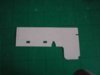
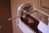
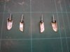
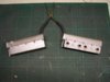
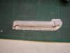
First the litho plate is marked out.


View attachment 262764


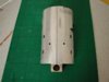
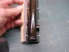
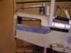
The slots are cut using a scalpel (No. 15 blade) and carefully sanded from the back to remove the “burs” leaving a very thin slot then bent around a length of piano wire.


View attachment 262765


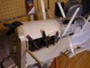
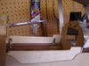
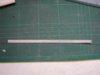
The flaps are bent out before the piano wire is removed. When the hinge has been glued in position it is faired in using cellulose stopper.


View attachment 262766


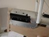
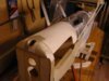
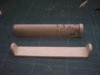
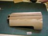
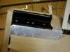
The lower cowl sections have had their litho plate covers attached and the insides painted with silver Solalac. I prefer to use coloured Solalac to fuel proof the engine bay because it is easier to see if you miss anywhere, also if you can see the inside through holes etc. it looks a lot more realistic than plain balsa.


View attachment 262767


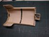
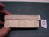
The sides are attached to the engine plate so things don’t look “square” because of the engine down thrust.


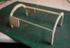
The lower cowl in position.


View attachment 262768


I’ll fit the dummy cylinder heads before I cover the top cowl with litho plate so I’m sure everything will fit together.
 

Attachments

  • cowl 12.jpg
    cowl 12.jpg
    1.6 KB · Views: 0
  • cowl 13.jpg
    cowl 13.jpg
    1.7 KB · Views: 0
  • cowl 14.jpg
    cowl 14.jpg
    2.2 KB · Views: 0
  • cowl 15.jpg
    cowl 15.jpg
    1.8 KB · Views: 0
  • cowl 16.jpg
    cowl 16.jpg
    2.5 KB · Views: 0
Grahame I doubt whether the model engine would take a four blader anyway,too much load,dont forget the real machines had slow revving engines with lots of torque to drive those big propellers.
 
Thread owner
Grahame I doubt whether the model engine would take a four blader anyway' date='too much load,dont forget the real machines had slow revving engines with lots of torque to drive those big propellers.[/quote']Barry

I assumed that Alan was talking about a static prop for display purposes only; at least I was.

Grahame

Apologies all round!

It’s just been pointed out to me that APC do a range of 4 bladed props; but they are quite expensive so I’ll definately be sticking with a 2 blader anyway.
 
Thread owner
A point worth mentioning is that the lower cowl consists of flat plates so for these I’ve used litho plate that hasn’t been annealed; it’s not as easy to work with but in its original state it will remain flat a lot better.


The dummy engine is now glued in position and a start made on the dummy attachment points.


View attachment 262769
 

Attachments

  • cowl 17.jpg
    cowl 17.jpg
    2.5 KB · Views: 0
An excellent build Grahame. The Se5a is an all time favourite of mine, and by the looks of things you are doing it justice, congratulations M8. :)
 
Thread owner
The top cowl is quite a complex shape so the first thing to do is to make a cardboard template, initially from the plan then adjusted as necessary to fit the actual model.


View attachment 262770


The left hand side was covered first using non-annealed litho plate cut to the above pattern. I suppose it says something about my building that the template needed some minor adjustment to fit the right hand side but then again I wouldn’t be surprised if the full size cowl needed a bit of tweaking to fit correctly!


View attachment 262771


The cowl is a fairly tight fit around the 2 dummy cylinder heads and with also having to accommodate the cabane bracing wires it is quite a fiddly job to get it into position but once there I think it looks good.


View attachment 262772
 

Attachments

  • cowl 18.jpg
    cowl 18.jpg
    1.3 KB · Views: 0
  • cowl 19.jpg
    cowl 19.jpg
    2 KB · Views: 0
  • cowl 20.jpg
    cowl 20.jpg
    2 KB · Views: 0
Status
Not open for further replies.
Back
Top