Theme editor

Scale Model Shop

SE5a CONSTRUCTION BEGINNING TO . . .

Status
Not open for further replies.
Thread owner
I’ve said before that I like to get the positions for the radio gear sorted out as early as possible in the build so as not to get any nasty surprises at a later stage, after all the whole purpose of the exercise is to produce a radio controlled model! Unfortunately, although I confirmed the principle for the aileron control very early on in the build, the practicalities of actually fitting it into the model could not be worked out then because I had no idea how much spring tension would be needed or how much “slack” the system would have.


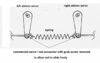
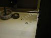
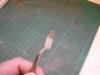
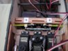
This is the design that I tested to prove the principle.


View attachment 263077


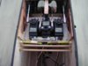
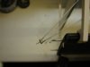
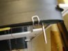
I fitted the spring temporarily using the inserts from an electrical connector strip and adjusted the tension as necessary. Because of the tension I had to reduce the length of the cable joining the top ailerons slightly then all worked nicely.


View attachment 263078


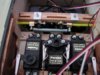
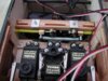
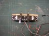
I was surprised to find that as with the elevators there was no noticeable tightening or loosening of the cables and the tension required was the same, ¼" plus a bit for safety; I’d expected to have to use about double as the one cable controls all 4 ailerons, runs round 4 pulleys and there is a lot more of it.


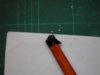
Fitting the spring the way I have done has given me an idea; I’m going to turn the design “inside out”, that is I’m going to attach the spring outside the servo arms not between them as originally intended. Doing it this way means I’ll be able to move the servos a lot closer together, which will mean less bending of the snake inners, which in turn will make for a smoother and more precise movement of the ailerons.


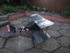
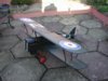
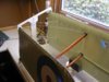
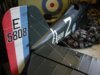
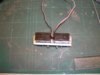
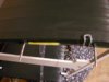
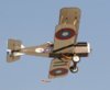
Having got to this stage I couldn’t resist the temptation to fit the wheels and take a couple of photos.


View attachment 263079


View attachment 263080


Looks a bit “naked” without all the wires, Lewis gun and a pilot!
 

Attachments

  • aileron linkage ).jpg
    aileron linkage ).jpg
    1.7 KB · Views: 0
  • assembled 3.jpg
    assembled 3.jpg
    2.5 KB · Views: 0
  • assembled 2.jpg
    assembled 2.jpg
    2.6 KB · Views: 0
  • aileron linkage 9.jpg
    aileron linkage 9.jpg
    2.6 KB · Views: 0
It's the photo we've all been waiting for! The SE5a looks beautiful assembled! I bet you can't wait to don the flying goggles, silk scarf and prepare for take-off!

The white lettering, red wheel covers and markings really do lift the dark green too. It looks superb!

I must admit that those paving slabs look a little incongruous though!
 
What amazes me apart from the brilliant job your doing with this build and the helps and tips your giving to others, is the fact you have time to photograph and write about it in such detail.
 
Grahame,

I am very impressed with the photo's, she does look the part indeed, Somewhat Ironic set against a hexagonal patio background and the Pfalz having already been mentioned as a possible next subject for you !!

I have a feeling those hexagons are going to be haunting you for a while yet !!

Regards.....Mark
 
Looks beautiful Grahame,it does not seem that long ago that you laid down those few few pieces.
 
Grahame, what can we say!! Beautifull does not do it justice! I am going to wait for the shots with the gun and the pilot fitted though to get the full impact of this amazing model.
 
Thread owner
Thanks for the comments; I’m glad I took the photos because the wings are off again for fitting the wires etc but at least I can visit the site and see what it looks like assembled. I have to admit that it’s not the best background but I’ll wait until the model is completely finished before take any more and hopefully

it’ll be warmer weather by then, believe it or not we had a dusting of snow here yesterday. I’m hoping to get permission to use Fishburn aerodrome, they’ve got some “old fashioned” hangers there so if I can get the perspectives correct it could look quite realistic.

I was discussing the aileron linkage today and was asked “why use the spring if there’s no slack?”. Well the first thing to say is that I said “there was no noticeable tightening or loosening of the cables” not quite the same thing, but anyway the cable needs to have some tension to keep it in the pulleys and make them rotate, without the spring this tension would have to be supplied by the servos working against each other. Stalled servos drain power from the battery very quickly and the result can be disastrous. I had considered using a true closed loop system with the cable itself providing the tension but I feel the set up would be quite critical; the spring gives that bit of leeway
 
Thread owner
The wings are now joined together and I’m very glad to say that it’s no problem attaching them to the fuselage; if it had turned out to be not viable to disassemble the model for storage in the shed I would have had a lot of grovelling to do to the better half!


I had thought that the wings would be quite “wobbly” when held in the frame but in fact the assembly holds itself in position quite well. The photo also gives a good view of the underside weathering and the inspection “window”.


View attachment 263084


The interplane struts are held in position with bent pins with only the bent section epoxied to the strut; if needs be it should be fairly simple to remove them. The struts only really need the pins to hold them in place until the model is assembled, after that the struts are always in compression so they really hold themselves in position on the pegs.


View attachment 263085


The front flying wires are permanently attached to the fuselage bracket; the 2mm stud goes through a hole in the fuselage side just above the front undercarriage leg and is held tight by a nyloc nut.


View attachment 263086


On the full size the rear flying wires are attached to the fuselage inside the lower wing stubs. This is impractical on a model of this size so these wires end inside the wing stubs joined by a length of brass tube.


View attachment 263088


The SE5a has a very thin wing section but the model has sufficient strength, thanks to carbon fibre spars and LE, to not actually need flying wires, except for show, so it is perfectly feasible to just leave the wires loose. I don’t really like that idea though as I feel they might “flap about” uncontrollably once the engine is running so I’ll devise a way of applying at least some tension; either flexible “tails” attached to the wires themselves or hooks on flexible wires inside the wing stubs, I’ve not decided as yet.
 

Attachments

  • bracing 3.jpg
    bracing 3.jpg
    1.4 KB · Views: 0
  • bracing 4.jpg
    bracing 4.jpg
    1.8 KB · Views: 0
  • interplane 9.jpg
    interplane 9.jpg
    1.6 KB · Views: 0
  • wing frame 5.jpg
    wing frame 5.jpg
    2.8 KB · Views: 0
Thread owner
For the last few days I’ve been experimenting trying to make the tail plane support wires from 24swg piano wire. I made various ends using brass and aluminium tube but none of them looked right; they were all too “chunky”. In the end I decided to try bending the wire to the exact length required, doing this meant there would only be 2 wires in the “ferrule”, which could also be a lot shorter as it isn’t functional. This was not my preferred method as I thought it would be a problem getting the bends in exactly the right place but as it turned out it wasn’t too difficult, of the 8 wires only 1 had to be scrapped and re made. The ends are made from a sort length of heat shrink tubing, which is very thin walled, painted silver; they still need to be “dirtied up” a bit but the overall effect is certainly a lot better than the fishing trace.


View attachment 263134


When assembling the model I have to connect the 4 aileron cable quick links, this is a bit awkward as there is only a relatively small gap between the centre section and the wing root rib. To make things easier I’ve made a small “ tool” to hold the links open, as a bonus it also stops the links disappearing into the wing tubes!


View attachment 263089


It is simply inserted into the link and turned through 45º. It’s easier to see how it works using a link that is not on the model.


View attachment 263090
 

Attachments

  • bracing 5 (2014_01_28 14_36_24 UTC) (2015_09_17 21_08_46 UTC).jpg
    bracing 5 (2014_01_28 14_36_24 UTC) (2015_09_17 21_08_46 UTC).jpg
    3 KB · Views: 0
  • tool 4.jpg
    tool 4.jpg
    1.2 KB · Views: 0
  • tool 1.jpg
    tool 1.jpg
    1.9 KB · Views: 0
Without a doubt a true work of art and a fine example of exactly what our hobby is all about. Many thanks for taking the time to teach and demonstrate. More so, thank you for sharing this masterpiece with us all!
 
Thread owner
The aileron linkage is now fully installed in the model and it all works fine! I still need to tidy things up a bit; I need to make new servo connectors because as I was fitting everything into the model I realised that once they’re glued into the snakes the servos would be very difficult to remove and knowing my luck one of them would pack up, I’ll also make better spring connectors,


Because I decided to modify the servo linkage by “turning it inside out” so to speak I was able to mount servos horizontally instead of vertically as I’d originally intended, which makes things a lot easier. The mounting plate is from 0.5mm galvanised steel with some 1/8th ply to improve the grip of the mounting screws.


View attachment 263091


I modified the mounting lugs to enable both servos to be held by the same grommets, this wasn’t strictly necessary but the assembly being that bit narrower does make it easier to fit into the fuselage. 2mm mounting studs are glued into some 1/8th spruce, which also helps to keep things straight.


View attachment 263092


The whole assembly fits between the front spars and is held in place by the 2 studs.


This photo is at neutral.


View attachment 263093


As the servos move, differential ensures they don’t work against each other whilst the spring keeps the cables under tension; only the “pull” servo is doing any work.


Full left


View attachment 263094


Full right


View attachment 263095


As each aileron servo has to operate all 4 ailerons with their associated cables and pulleys I needed “high torque” servos. Because I wasn’t convinced that the system would actually work satisfactorily when installed in the model and I didn’t want to waste money, I decided to buy a pair of “cheap” Supertec servos.


These are very powerful, giving 7.4 kg/cm torque at 4.8volts and have no trouble at all moving the ailerons, but they do sound a bit “agricultural”. I now think maybe I should have had the “courage of my convictions” and gone for either Futaba or JR. Can I now justify the extra expense?
 

Attachments

  • aileron linkage 13.jpg
    aileron linkage 13.jpg
    3.4 KB · Views: 0
  • aileron linkage 14.jpg
    aileron linkage 14.jpg
    3.4 KB · Views: 0
  • aileron linkage 12.jpg
    aileron linkage 12.jpg
    3.3 KB · Views: 0
  • aileron linkage 11.jpg
    aileron linkage 11.jpg
    2.3 KB · Views: 0
  • aileron linkage 10.jpg
    aileron linkage 10.jpg
    2.1 KB · Views: 0
Thread owner
To answer the rhetorical question posed at the end of my last post; “yes I can!” In fact having given it some consideration I changed the question I asked myself to “having spent the best part of 2 years building this model can I afford not to buy better servos?”


I’ve bought a pair of Futaba S3305, they have slightly less torque at 7.1 Kg/cm but are quicker, 0.25 sec/60º as opposed to 0.33sec for the SuperTec; I’d thought that the 0.11 sec that the SuperTec were slower than “standard” wouldn’t really be noticeable but it certainly was and importantly the Futaba don’t have that “agricultural” sound. I’m a lot happier with them notwithstanding the extra cost!


I’ve also replaced the 148s with ball raced S3001Bs.


In order to rig and connect the aileron cables to the servos the model has to be held upside down; before I fitted the Lewis gun I just used beanbags for support and protection but obviously this was not a permanent solution so I've made a stand.


The stand is a length of 75mm x 50mm timber and “Y” shapes soldered up from15mm copper pipe with foam insulation for protection.


The stand will also come in handy for routine maintenance etc. as it holds the model securely whichever way up it is!
 
Grahame is it really two years ? where did that time go to,but the fruits of your labours show beautifully in your latest picture here,it just says I want to fly and get some air under my wings !

That is a clever maintenance stand.
 
I love this thread! It's great to see things progressing.

A dumb question but where did the pilot come from? (or have I missed that part somehow?)
 
Thread owner
The pilot’s doing a bit of “moonlighting”, when he’s finished his day job fighting the Hun he jumps back into his Parnall Elf for a bit of relaxed flying!

A 1/6th “full body” from Pete Richardson (Pete’s Pilots), he now sells on ebay with what appears to be a drastically reduced range of pilots. I’ll have to email him to see if he does in fact still do “full body” pilots; they’re not shown on the web site.

I’ve had the wings on and off the fuselage several times sorting out the aileron linkage etc. with no problems, until today that is! The secret is to keep a small amount of tension in the cables whilst assembling the model, which I did by pulling on the linkage as I fed the wing pegs into their tubes, but I must have got a bit complacent today as one of the cables came off it’s pulley. After a considerable length of time and much cursing I managed to get it back onto it’s pulley using thin wire fed through the exit slot for the cable: I now have much more admiration for the “ship in a bottle” modellers! I’ll have to devise some sort of mechanical device to keep the tension; I wouldn’t want this to happen again as I’m getting ready to go to the flying field.

If you’ve enjoyed this thread then you’re in for a treat! Follow the link below for a build thread for a radio control / control line hybrid SE5a by Steve (smcouch77); the attention to detail is unbelievable; I just wish I’d known about this thread earlier.

http://www.rcuniverse.com/forum/m_5029692/mpage_1/key_/tm.htm
 
Grahame,

If you get stuck for a Pilot try A.H. Designs via the following Link:

http://www.thepilotpeople.co.uk/

He does a full range of Pilots including one which will be spot on for the SE5a.

I met the maker, Alan, a number of years ago now and have had a full tour of his workshops -He has some absolutely Fantastic Models and his Pilots are extremely Lightweight and well made too.

He lives just a Mile from my Parents House where he now has his workshops. (Alan can be seen on the Home page outside his house with one of his Kits he produces - The Extra 300)

Regards.......Mark
 
Sorry for being impatient but - How long is it until the test flight and I'm sure a lot of the other members here are desperate for some walkaround shots of the aircraft in it's current state of completion! It's going to look beautiful in flight too. Can't wait for some in air shots too!
 
Thread owner
Thanks for the link to AH Designs, I’ve never actually seen one of their pilots but I have to say they look good on the website. I won’t invest in a new pilot until after the first flight, I’m not superstitious but you never know I might not need one, it could end up in a binbag! Talking of the first flight, there’s at least another 3 months of winter to get through before I even think about that, then I like to get my thumbs coordinated with my brain again using the AcroWot. As for some “walk around” shots, I think that’ll have to wait for better weather; the front room is big enough so just maybe, once the Christmas decorations are out of the way, and if I grovel enough you never know your luck.


The model is now all but finished; the “teething troubles” with the rigging has been sorted out by using a mechanical tensioner to keep the cables in the pulleys at all times. The problem is that there is not much room between the wing and the centre section whilst rigging, this taxed the brain a bit until I literally used some “lateral thinking” and although I’ve only used it a couple of times I don’t envisage any more problems.


This is obviously just the prototype; when I make the rest of the set they’ll use springs not elastic bands! It doesn’t need much tension, in fact the elastic band is really too strong.


When in the storage position the ailerons are at neutral and the quick links just protrude from the wing tubes.


View attachment 263096


When connecting an aileron cable it is pulled out from the wing tube, which of course pulls the other connector into its wing tube, the metal “staple” is to stop the thread cutting into the rib.


View attachment 263097
 

Attachments

  • tensioner 2.jpg
    tensioner 2.jpg
    2.3 KB · Views: 0
  • tensioner 1.jpg
    tensioner 1.jpg
    2.4 KB · Views: 0
That's a very ingenious setup, Grahame.:emo1: I think you would be safe to go ahead with the new pilot. This bird is going to fly great!

Steve
 
Thread owner
As I said in my last post, the model is all but finished and there’s a long time to go until the flying season, so the question is what to do in the meantime? Reading through Steve’s build thread on RC Universe this photo of his SE5a got me thinking; a Cooper bomb rack would while away the hours!


View attachment 263098


I was a bit concerned that my SE5a was “piling on the pounds” with all the detailing work so I contacted Steve to ask what his weighs as it obviously flies very well. A quick calculation for relative sizes gave me a target weight of 4.2Kg, so I stood on the scales holding the model with my pockets full of batteries, servos and a Laser 70 and got a weight of 3.8Kg. The model actually feels quite heavy but there’s a lot of wing area so I’m sure the model can take the extra weight, but whether or not I manage to sort out the complexities of designing and building the bomb rack remains to be seen!
 

Attachments

  • Hc91911.jpg
    Hc91911.jpg
    1.8 KB · Views: 0
Status
Not open for further replies.
Back
Top