G
Guest
Guest
Hi while the varnish dries on the BA-64 and I get outy to find a frame to use I decided to crack on with the
T 38.
A
Like other light tanks of its time, the T-38 was designed for reconnaissance and infantry support roles. As a scout tank the T-38 had the advantages of a very low silhouette and good long-range mobility through its ability to swim. The T-38 was also intended to be air-portable; during the Kiev maneuvers in 1936, the tanks were transported by Tupolev bombers, mounted under the fuselage. Infantry battalions were each issued 38 T-38s, with 50 being designated for each airborne armored battalions. However, the thin armour and single machine gun armament made the tank of only limited use in combat. A lack of radios in most T-38s was a serious limitation for a reconnaissance vehicle. The T-38 also struggled with carrying any excess cargo across water. In fact two infantrymen of 120-150 kilos would cause the commander's hatch to flood, sinking the vehicle ! These flaws were to be fixed by the T-38's successor, the T-40
A total of 1,228 T-38 tanks were built from 1936 to 1937, with an additional 112 made in 1939 after a two-year break in production.
Designed by Nicholas Astrov and N Kozyrev and built at Factory No 37 Moscow.
Weight was 3.3 Tonnes.
Powered by a Gaz
AA 4-cylinder inline gasoline engine
40 hp (30 kW). it could reach speeds of 40 km/h
3.78 meters in length and 3. 33 meters in width it was nearly square in shape.
Height was 1. 63 mtrs, so very low.
The armament was a 7.62mm DT machine gun.
So the box .

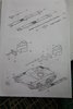
Sprues andinstructions a piece of paper with some doubtful drawings on. Sprues are not numbered as such but you refer to the piece of paper which is not too bad. But the drawings are of no help when attempting to fir some parts as you will see.

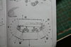
You start with the first page, this part is quite self explanatory.

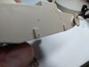
I decided to leave all those bits that get knocked off until the tracks are on and I'm ready to paint, the only parts fitted were 2 x of No 30, as some idlers are mounted on them.
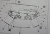
This is where the abrupt end of modeling took place. Parts 23 are supposed to fit where the lines go, but I have no idea where on the moulding on the body they go. At this point I shall have to upload this and then post some camera shots explaining the problem.
T 38.
A
Like other light tanks of its time, the T-38 was designed for reconnaissance and infantry support roles. As a scout tank the T-38 had the advantages of a very low silhouette and good long-range mobility through its ability to swim. The T-38 was also intended to be air-portable; during the Kiev maneuvers in 1936, the tanks were transported by Tupolev bombers, mounted under the fuselage. Infantry battalions were each issued 38 T-38s, with 50 being designated for each airborne armored battalions. However, the thin armour and single machine gun armament made the tank of only limited use in combat. A lack of radios in most T-38s was a serious limitation for a reconnaissance vehicle. The T-38 also struggled with carrying any excess cargo across water. In fact two infantrymen of 120-150 kilos would cause the commander's hatch to flood, sinking the vehicle ! These flaws were to be fixed by the T-38's successor, the T-40
A total of 1,228 T-38 tanks were built from 1936 to 1937, with an additional 112 made in 1939 after a two-year break in production.
Designed by Nicholas Astrov and N Kozyrev and built at Factory No 37 Moscow.
Weight was 3.3 Tonnes.
Powered by a Gaz
AA 4-cylinder inline gasoline engine
40 hp (30 kW). it could reach speeds of 40 km/h
3.78 meters in length and 3. 33 meters in width it was nearly square in shape.
Height was 1. 63 mtrs, so very low.
The armament was a 7.62mm DT machine gun.
So the box .
Sprues and
You start with the first page, this part is quite self explanatory.
I decided to leave all those bits that get knocked off until the tracks are on and I'm ready to paint, the only parts fitted were 2 x of No 30, as some idlers are mounted on them.
This is where the abrupt end of modeling took place. Parts 23 are supposed to fit where the lines go, but I have no idea where on the moulding on the body they go. At this point I shall have to upload this and then post some camera shots explaining the problem.