Theme editor

Scale Model Shop

Dave Ward's 1/35 Krupp L3H163 Early war Heavy Truck

Status
Not open for further replies.

Dave Ward

New member
Joined
Apr 27, 2018
Messages
10,549
Reaction score
43
Points
0
1/3
Thread owner
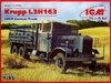
After the Revell/ICM 1/48 Mig-25, I'm going to build the 1/35 Krupp 6 X 4 Heavy Truck, also from the ICM stableView attachment 314893
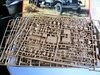
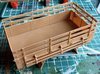
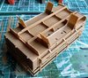
The box is full of plastic - the construction is pretty complex, the chassis is flat pack - no slide moulding!
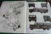
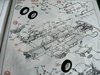
The instructions are busy...................... 2 finish variants - both grey early warView attachment 314890View attachment 314895View attachment 314894
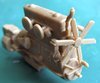
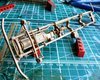
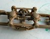
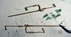
Some of the parts are fragile - I can see problems getting this off the sprues in one piece! - Rear axles brake linkages...........View attachment 314891
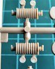
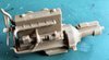
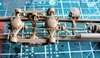
Some neatly moulded parts - springs, & fan for the complete engineView attachment 314897View attachment 314892

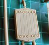
Radiator...............View attachment 314896
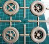
The wheels and tyres are one piece - no vinyl here! ( good!!! )View attachment 314898

Looks like it will be a pretty fiddly build, I've made a few ICM trucks, and as long as the chassis is built square, then all should be well
Construction will start shortly!
Dave
 

Attachments

  • box sprues.jpg
    box sprues.jpg
    4.2 KB · Views: 0
  • brake links.jpg
    brake links.jpg
    2.5 KB · Views: 0
  • fan.jpg
    fan.jpg
    4.5 KB · Views: 0
  • icm krupp.jpg
    icm krupp.jpg
    4.5 KB · Views: 0
  • instr 01.jpg
    instr 01.jpg
    3 KB · Views: 0
  • instr 02.jpg
    instr 02.jpg
    3.4 KB · Views: 0
  • radiator.jpg
    radiator.jpg
    3.3 KB · Views: 0
  • springs.jpg
    springs.jpg
    3.4 KB · Views: 0
  • wheels.jpg
    wheels.jpg
    4.8 KB · Views: 0
Thread owner
Finally managed to open the box, and get some parts together. The engine is quite an assembly, none of which will be seenView attachment 315373View attachment 315372
I've only really assembled this for location of other bits - exhaust pipes etc.
The chassis consist of side rails, and cross members, the instructions are a bit vague, and you have to puzzle out how some parts fit! Side rails, one with a winch, and the central member with transfer box.
View attachment 315374
I've left off the running boards/mounts - I've made ICM trucks before, and fitting these bits now is asking for them to break off - they seem positioned right where the fingers fall! They can be added much later in the build.
The model has 296 parts - all closely packed on the sprues, and the numbering is a little odd in places, so careful study is needed - I couldn't find part 104, but worked out that is actually meant to be 102, just by process of elimination
Dave
 

Attachments

  • rails.jpg
    rails.jpg
    1.7 KB · Views: 0
  • engine 02.jpg
    engine 02.jpg
    3 KB · Views: 0
  • engine 01.jpg
    engine 01.jpg
    2.4 KB · Views: 0
Nothing like a puzzle is there Dave. A sence of achievement when you work out where it is.
I shall grab a front seat.
John.
 
Dave, I'd do the same for parts that are not visible but are needed for location points. Most I would do is spray them black after so the shody work can't be seen accidentally.

Cheers,
Richard
 
Dave,
Just looking at the sprues makes me a bit dizzy. Think I'll take a seat a bit further back near the door in case I have an attack of vertigo. :upside:
Cheers,
Rick H.
 
Thread owner
The cross members are added to the rails, and left on my Lego blocks, to really dry square.
Some of the components are way over engineered - the towing eye cross member has 7 parts! ( R )
View attachment 315511
While that is drying, I decided to do the load bed......................View attachment 315512View attachment 315513

Again, the instructions are a bit vague, and careful study is needed to ensure you don't get the base wrong way round - still, when that's figured out, the fit is good. There are quite a few attachment points to clear up. the plastic is reasonably soft & easy to work. The instruction sequence would have you add the spare wheels on the underside, but that would really complicate painting.
Tomorrow, it will be the suspension & running gear - some of it looks very 'busy', so I hope I have steady hands!
Dave
 

Attachments

  • chassis.jpg
    chassis.jpg
    1.9 KB · Views: 0
  • load bed 01.jpg
    load bed 01.jpg
    3.9 KB · Views: 0
  • load bed 02.jpg
    load bed 02.jpg
    4.6 KB · Views: 0
Hi Dave
Can't go wrong with a big truck. Looks to have nice crisp detail. Even the springs look nice. Good to have one piece PLASTIC wheels and tyres :smiling3:
Jim
 
Thread owner
Front axle assembled, off the chassisView attachment 315561
The engine, front axle & exhaust added to the chassisView attachment 315562
Now, the rear suspension - I thought it was going to be tricky, and I wasn't wrong!
The brake linkages, I thought I was going to have trouble in getting them off the sprues...........
One came off in one piece! JOY! - but the next, 3 pieces!View attachment 315560
According to the instructions the rear axles should be assembled off the chassis, but after a few tentative trials, I decided that wasn't feasible!. I decided to attach the bits to the chassis, as a solid base. Even so, I could have used an extra hand during construction. It may not look much, but this took about 1/2 hour to assemble!
View attachment 315563
This will dry overnight, then I will add all the linkages - it needs solid bases for these flimsy parts. The Krupp is proving more of a challenge than I anticipated!
Dave
 

Attachments

  • brake linkages.jpg
    brake linkages.jpg
    1.9 KB · Views: 0
  • front axle.jpg
    front axle.jpg
    3.3 KB · Views: 0
  • front chassis.jpg
    front chassis.jpg
    4.7 KB · Views: 0
  • rear axle.jpg
    rear axle.jpg
    2.8 KB · Views: 0
Dave .
That's a neat idea with the leggo, ........ grandchildren had better watch out.
How you did the removal from the sprue of those linkages with out it breaking is a marvel. I find that half way through when you think you've cracked it it snaps in two !!!! and I was using the saw. Those look like they would snap just being looked at .

John .
 
Thread owner
I got a box of Lego ( just blocks ) from an after Christmas sale - You can make all sorts of useful jigs & supports, but of course, they stick together with normal glue, so the attrition rate is pretty high.
Removing bits from sprues? - well, if I can support the part on a solid backing, then a sharp scalpel works. If the part is an odd shape, or you can't support it, I use sprue cutters, making sure that the cut is square to the part. I have a small sharp pair, that I only use on fragile parts. I've never had much success using razor saws. Of course, a lot depends on the plastic - The early MiniArt models were a nightmare of brittle plastic, that broke as soon as you looked at it. ( later MiniArts aren't that bad )
Dave
 
Dave.
That's where I go wrong then, no support. Will remedy that in future.
John,
 
Dave,
Coming along very nicely. I'm wondering if you could use brass rod to substitute for the plastic linkages? I don't know if you can get brass turnbuckles in that scale or perhaps scratch something up...might save a lot of hair pulling!
Cheers, Rick H.
 
Thread owner
I repaired the broken brake linkage with TET, then strengthened it with CA.................View attachment 315606

Then, the assembly of the rear axles & brake linkages. This was a real puzzle at times, the instructions being a bit vague, then actually fitting the parts!!
View attachment 315605
I have to say, I did not enjoy this part of construction! It was very fiddly, Four hoops over the axles all broke, getting them off the sprue, the torque links broke, and one had to be replaced, and to cap it all, I broke the steering column off, and it's still AWOL. All of this underside will of course be largely unseen - I can't wait to get it all primed.
I think that is the worst of the construction over!
Dave
 

Attachments

  • rear suspension assy.jpg
    rear suspension assy.jpg
    3.6 KB · Views: 0
  • repaired link.jpg
    repaired link.jpg
    2 KB · Views: 0
Thread owner
Lee,
I was puzzling over where I had seen a similar rear suspension with the horizontal spring, then I remembered - the Krupp Protze - I have a Tamiya one in the stash.
Dave
 
I've had some success using a heated blade to remove fiddly parts from sprues. I don't cut the part itself, I just release the sprue runners from the main sprue frame. Using a heated blade means you don't put any pressure on the parts and it also leaves you free to manipulate whatever cutters you are using to cut the part itself free.
 
Thread owner
I'm afraid this one is going back into the box for the time being. I've made several attempts to go on with the build, but I've lost interest, and forcing myself to finish this will end up with something I'm not happy with. I will return to this, just not yet.
I'm going to start another build, but not blog it. I joined the forum in April, and I've blogged every build I've done since then, so time to miss one or two out. I'm still going to haunt the site, though........................
Dave
 
Sorry to hear that Dave. I've always enjoyed following your WIPs.
Cheers, Rick H.:sleeping2:
 
Status
Not open for further replies.
Back
Top