

You are using an out of date browser. It may not display this or other websites correctly.
You should upgrade or use an alternative browser.
You should upgrade or use an alternative browser.
Jim R's German Field Kitchen
- Thread starter Jim R
- Start date

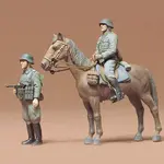


Hi Jim, good choice of the Tamiya Field Kitchen. I remember it being a very detailed kit and lended itself to painting washes and dry brushing very well. If you were adventurous you could fill the center vat with tinted varnish and bits of painted plastic shavings to form a stew seen with the cover open. Coffee and steamed vege in the side containers. The horses you bought are excellent for rested horses...have them away as far as possible from the figures if you are afraid of scale. Work horses are bigger anyway. Reshaping animals is not an easy feat as getting human anatomy right is already challenging for many.
The new set from Tamiya gives great figures. The older resting set is rather good as well...one of Tamiya's earliest attempt of their new range of figures.
Look forward to more of what you've started...it's nearly a shake and bake process.
Cheers,
Wabble
The new set from Tamiya gives great figures. The older resting set is rather good as well...one of Tamiya's earliest attempt of their new range of figures.
Look forward to more of what you've started...it's nearly a shake and bake process.
Cheers,
Wabble

Thanks for all your input and suggestions.
Before the bottom of the kitchen can be attached the chimney and the cooking pot have to be fitted. The pot lid will be open so some "stew" was needed. I used Milliput to make some potatoes, sausage etc. I'll pour in some coloured resin later for gravy. Thanks Richard for the suggestion but I was there already
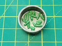
I used up the left over putty for bread and apples.

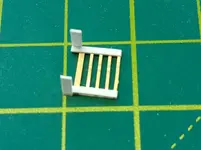
Now as is clear from the box art and other reference photos there should be a fold down step on the right hand side. Missing from the kit. So that was scratch built.
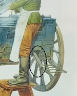
In the photo above the sticky out thingy, ringed, is clear but I haven't a clue what it is. It's only on one side. Any ideas???
Thanks again.
Before the bottom of the kitchen can be attached the chimney and the cooking pot have to be fitted. The pot lid will be open so some "stew" was needed. I used Milliput to make some potatoes, sausage etc. I'll pour in some coloured resin later for gravy. Thanks Richard for the suggestion but I was there already
I used up the left over putty for bread and apples.
Now as is clear from the box art and other reference photos there should be a fold down step on the right hand side. Missing from the kit. So that was scratch built.
In the photo above the sticky out thingy, ringed, is clear but I haven't a clue what it is. It's only on one side. Any ideas???
Thanks again.

Darian Frey
Active member
1/3
nice looking stew and well spotted sorting that step out.


I was intrigued by that sticky out thing, went looking but still none the wiser
Found some great pics tho if they are of use
 www.landmarkscout.com
Found some great pics tho if they are of use
The Große Feldküche Hf. 13 – German Large Field Kitchen | LandmarkScout
The Large Field Kitchen Hf. 13 is an updated version of the Hf. 11 field kitchen which was used during
www.landmarkscout.com
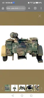
Thanks Paul. That website is very good.
I did wonder if the sticky out thing was some kind of inbuilt stand. Could be lowered to support the kitchen if the wheel needed changing. That would fit with your finding that it could be fitted to either side.
I did wonder if the sticky out thing was some kind of inbuilt stand. Could be lowered to support the kitchen if the wheel needed changing. That would fit with your finding that it could be fitted to either side.
I was thinking if you lifted up the tow hitch would you get a point where it would try to flip over backward...... Would the sticky out thing prevent that?....... Or if you could raise it up would it make emptying the fire boxes easier?

Jim your making me hungry already and I just had Breakfastused Milliput to make some potatoes, sausage etc

I remember JR years ago building one of these and is this the one he actually tried to cook on it and set his dio on fire??

- Joined
- Dec 28, 2023
- Messages
- 2,876
- Location
- Swale Kent UK
- First Name
- Peter
1/3
I was thinking this, some sort of anti tip bar, bit like an anti wheelie bar on a bike, or a dragster.....?I was thinking if you lifted up the tow hitch would you get a point where it would try to flip over backward...... Would the sticky out thing prevent that?....... Or if you could raise it up would it make emptying the fire boxes easier?
Thanks for all suggestions on the sticky out thing. For the moment at least it will be ignored. It's not in the kit anyway 
I mixed up some resin and added a little pigment and dripped it into the cooking pot around the "food". I then painted up some potatoes and sausage. The chimney and the pot were fitted and then the base went on.
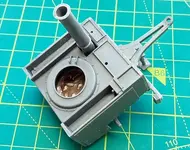
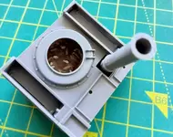
Very unusual for Tamiya but there was a gap between the chassis and the springs. I checked and checked but it's definitely there.
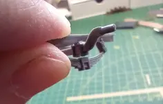
A tiny styrene block sorted it but strange anyway.
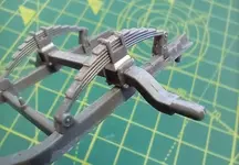
The rest of the underside went together like a breeze.
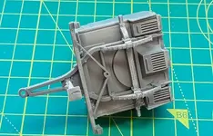
Thanks again
I mixed up some resin and added a little pigment and dripped it into the cooking pot around the "food". I then painted up some potatoes and sausage. The chimney and the pot were fitted and then the base went on.
Very unusual for Tamiya but there was a gap between the chassis and the springs. I checked and checked but it's definitely there.
A tiny styrene block sorted it but strange anyway.
The rest of the underside went together like a breeze.
Thanks again

Actually I believe the gap was supposed to be between the axle & frame. The axle is attached to the spring and not the frame to allow the suspension to work. May be an error in instruction.
OK. Thanks to Paul being eagle eyed and having an understanding of how suspension works there is a c***_*p.
However I don't think it was entirely down to me.
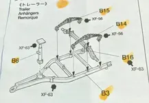
The instructions show the axle (part B16) attached to the chassis rails (part B3), there are pin and socket location points. It then shows the springs (parts B15 and B14) attached at each end to the chassis and also to the axle. As I see it the axle should only be attached to the springs and NOT to the chassis.
Am I right or am I still missing something?
However I don't think it was entirely down to me.
The instructions show the axle (part B16) attached to the chassis rails (part B3), there are pin and socket location points. It then shows the springs (parts B15 and B14) attached at each end to the chassis and also to the axle. As I see it the axle should only be attached to the springs and NOT to the chassis.
Am I right or am I still missing something?

1/3
Could well be the pin was a guide to stop the axle being forced sideways. Ie it could move up and down freely and wasn’t fixed. Railway wagons used similar technology, axle boxes sliding in a groove.OK. Thanks to Paul being eagle eyed and having an understanding of how suspension works there is a c***_*p.
However I don't think it was entirely down to me.
View attachment 1295781
The instructions show the axle (part B16) attached to the chassis rails (part B3), there are pin and socket location points. It then shows the springs (parts B15 and B14) attached at each end to the chassis and also to the axle. As I see it the axle should only be attached to the springs and NOT to the chassis.
Am I right or am I still missing something?
Legal Notice
scalemodelling.co.uk is a privately operated online discussion forum. All content posted by members reflects their own views and opinions and does not necessarily represent those of the forum owners or administrators. While reasonable efforts are made to moderate content, no responsibility is accepted for user-generated material. By using this site, you agree to comply with UK law and the forum rules.