Theme editor

Scale Model Shop

Pocher Porsche 917 1/8 Scale

Thread owner
IMG_3226.png Click image for larger version  Name:	IMG_3233.jpg Views:	1 Size:	351.8 KB ID:	1248845 Click image for larger version  Name:	IMG_3233.jpg Views:	1 Size:	351.8 KB ID:	1248845 Another quick update the top section of the subframe has now been added. This was another PIA and there was only two pieces to add. Hopefully that’s the engine finished as we are now moving onto the dashboard
 
Thread owner
Click image for larger version  Name:	IMG_3344.jpg Views:	0 Size:	287.1 KB ID:	1249494 Click image for larger version  Name:	IMG_3346.jpg Views:	0 Size:	351.0 KB ID:	1249495 Click image for larger version  Name:	IMG_3312.jpg Views:	0 Size:	242.0 KB ID:	1249497 Click image for larger version  Name:	IMG_3312.jpg Views:	0 Size:	242.0 KB ID:	1249497 Click image for larger version  Name:	IMG_3344.jpg Views:	0 Size:	287.1 KB ID:	1249494 Click image for larger version  Name:	IMG_3344.jpg Views:	0 Size:	287.1 KB ID:	1249494 Click image for larger version  Name:	IMG_3344.jpg Views:	0 Size:	287.1 KB ID:	1249494 Click image for larger version  Name:	IMG_3344.jpg Views:	0 Size:	287.1 KB ID:	1249494 
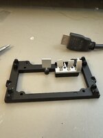
So we’ve moved onto the dashboard and the bottom tray of the car which will include the accelerator break and clutch along with the steering mechanism. First off is to apply the decals to the dashboard before doing this. I gloss varnished the areas that the decals were gonna sit on so they stick better. Each decal is separate and has to be treated as such and due to the nature of their placement you can’t just slide them off the backing paper you have to actually use some fine grip tweezers to grip hold of the decal once it’s separated from the backing sheet and place it onto the model
after this I applied Microsol decal setting solution red labelled bottle to the decals to flatten them down onto the surface and look like they were actually painted
once this was done I assembled the rest of the dashboard along with the Steering wheel and the rack & pinion assembly which is not the greatest of things and had issues with lining up the steering wheel to dead centre due to the nature of the teeth on the pinion
This was then added to the main bottom of the car along with the assembly of the accelerator brake and clutch pedals and a foot rest which unlike the other three did not have a spring attached to it why they’ve put springs on these I have no idea as they are going to be totally inaccessible when the car is fully built but they actually work so who am I to argue
finally the pedal assembly is attached to the bottom of the car. I did start assembling the shock absorbers and calipers ready for the brakes but unfortunately, I am missing the two front springs and until pocher / Hornby hobbies send me some replacements that’s as far as I can go so we could be waiting up for two weeks for the replacement parts. That’s assuming I’ve got them in stock if they haven’t then they’re gonna take even longer
once again, apologies for the way the photos have come out there above the text and they’re all over the place so you’ll have to make your own interpretations of how it should look in the sequence to my way of thinking I put the text in first hit a couple of returns and then input the photographs but this program seems to put the photographs above the text so next time I’m gonna put the photograph in first and then add the text afterwards and see if it reverses it again
 

Attachments

  • IMG_3321.jpg
    IMG_3321.jpg
    159.7 KB · Views: 0
Last edited:
Thread owner
Click image for larger version  Name:	IMG_3434.jpg Views:	0 Size:	273.2 KB ID:	1250408 Click image for larger version  Name:	IMG_3436.jpg Views:	0 Size:	357.8 KB ID:	1250409 filedata/fetch?filedataid=248131
wAAACH5BAEKAAAALAAAAAABAAEAAAICRAEAOw==
With the arrival of the springs I can now progress. These have now been fitted as you can see from this picture next up are the brake discs which have been moulded with holes shown in them as it’s totally impractical to drill out all these holes due to the back of the discs being ribbed I have used the old modellers trick of painting in the holes and then removing the excess paint using a cotton move swab dipped in isopropyl alcohol. This gives the effect of the being drilled through the discs. There is some controversy as to whether these actually were drilled or not, but as Pocher has decided to mould them as holes I have followed their lead and painted them to make them look like holes if you also look the holes form a fan shape now I think the spinning should be to the rear
if you look at the close-up of one of the finished Discs, you can see the shape that the holes make to my way thinking that one is a passenger side front or rear brake or depending on how you look at the car it’s either the left or the right so I don’t know how you do a car. left or right do you look at a car from the front and say that it’s left and right, would you look at it from the rear and say that’s left and right because they would be mirror opposites look at the 8 finished discs they clarly make fan patterns the quartet at the top are what I call the top left and bottom right match each other and the fan pattern is spinning in a left to right direction this to me indicates these are the front and rear passenger side or left side when viewing the car from behind brake discs the remaining 4 would be for the drivers side or right hand part of the car when viewed from the rear
​​​​​Apologies again for the Photo layout I cannot figure out why this program decides to put the photos above the text every time this is becoming an annoyance

Click image for larger version  Name:	IMG_3436.jpg Views:	0 Size:	357.8 KB ID:	1250409
 

Attachments

  • IMG_3434.jpg
    IMG_3434.jpg
    273.2 KB · Views: 0
  • IMG_3434.jpg
    IMG_3434.jpg
    273.2 KB · Views: 0
  • IMG_3434.jpg
    IMG_3434.jpg
    273.2 KB · Views: 0
  • IMG_3436.jpg
    IMG_3436.jpg
    357.8 KB · Views: 0
Last edited:
I'm enjoying the updates and really appreciate you sharing the process on a kit that looks fantastic.

With regard to the pictures, I've found that if you upload all the pics you want to put in the post before you start writing then it's fairly straightforward to ensure the cursor is where you want the picture to go when you click on the 'size' of photo you want to add. Hope that helps!

Nick
 
Thread owner
Click image for larger version  Name:	IMG_3456.jpg Views:	1 Size:	290.1 KB ID:	1250557 Click image for larger version  Name:	IMG_3456.jpg Views:	1 Size:	290.1 KB ID:	1250557 
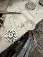
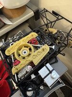
Now added the discs to the chassis subframe along with the brakes and the intercooler and associated pipework oh and also added the brake cooling duct pipe work as well see attached picture I did some additional painting on this one as per what Nigel has done on his website that was to paint the tops of the bottles blue with a silver band around the middle of them and to repaint the intercooler pipework black and just leave the union joints as aluminium then to finally finish it off, I gave it a black wash using Mig Ammo black oil wash across the grill hatchings I also need to clean up the flocking on the top of the dashboard I will do this using a bit of Tamiya masking tape then once I done it to cover it with plastic so it stays clean until it’s covered by the top part of the body work of the car
Click image for larger version  Name:	IMG_3456.jpg Views:	1 Size:	290.1 KB ID:	1250557
 
Last edited:
Thread owner
IMG_3492.jpg IMG_3491.jpg IMG_3477.jpg IMG_3489.jpg IMG_3481.jpg IMG_3476.png

Hello everybody remember me sorry for the lack of any updates but I’ve been ill with first off the coronavirus which knocked me out for at least a month. Then I went down with some respiratory problem where I was constantly coughing which made working on models impossible that lasted for about another month and I’ve only just got back into modelling after a month of no Mojo so here we go with the continuation of the Porsche 917 K
When I last left you, we just fitted the front, presumably hydraulic fluids for the steering etc next up is the coils for the rear bulkhead these were completely the wrong colour and as per what Nigel is doing on his Nigel‘s modelling bench as I’m following his build as well as he has lots of useful tips. Hope you read this Nige because I am following what you’re doing even though you’ve probably finished yours by now anyway I digress the coils should be blue with a silver band and a brown top to represent Bakelite plastic wasn’t around in them days like it is today once these were painted they were mounted into the bulkhead along with some other bits which have been painted as well then the bulkhead was mounted into the back of the subframe presumably formed a firewall between the engine and the driver
Next instalment will be the fitting of the rear bulkhead to the back of the drivers subframe and assembling the seats along with the seatbelts
 
Thread owner
Continuation of the Porsche 917 build fitting the seats
So this time we are going to be fitting the seats into the subframe along with the seatbelt and adding the rear firewall bulkhead to the back of the subframe
the seatbacks were painted black as opposed to leave them red and I then measured the lengths of the seatbelts required and cut those appropriately and then added the buckles. As you can see from the pictures. These were then mounted onto the seat. The side belt should be mounted to pivot points on the floor, but there are nothing on the model to allow this so I just wrapped them around the side of the seat as per what Nigel did on his
IMG_3540.png IMG_3544.jpg IMG_3570.jpg IMG_3570.jpg IMG_3584.jpg IMG_3568.jpg IMG_3570.jpg
 

Attachments

  • IMG_3542.jpg
    IMG_3542.jpg
    260.5 KB · Views: 0
Thread owner
I don’t know what’s quite happened here, but I tried an idea that somebody said put the pictures in first and then the text afterwards and I couldn’t add any text into the old post so it’ll have to come into this one for the pictures that are on their own
So next up is the oil and fuel system piping Along with the fuel pipes injector system as well those are the clear plastic pipes you can see and they were a right PIA to deal with as a silicone nothing sticks to them so they’re mostly held on with a wing and a prayer along with some CA glue
The clear piping should be attached to the fan assembly on the outside, but as there’s no facility for this in the model, what I done was wrapped them around the fan assembly as best I could
These clear plastic pipes should represent the injection system as such there is a firing sequence but it was so awkward to deal with that. I haven’t bothered to follow it and you can’t see where the pipes go from either once they’re assembled and attached so I couldn’t see the point of it
This little sequence took around three hours to complete after which each sub assembly was added to the subframe and then the engine was finally bolted onto the end of the subframe so we now have an almost complete chassis. Next step will be the adding of the parcel shelves more on that in the next post
 
Thread owner
Click image for larger version  Name:	IMG_4631.jpg Views:	0 Size:	254.9 KB ID:	1265092 Click image for larger version  Name:	IMG_4630.jpg Views:	0 Size:	337.6 KB ID:	1265093 Click image for larger version  Name:	IMG_4631.jpg Views:	0 Size:	254.9 KB ID:	1265092 Click image for larger version  Name:	IMG_4631.jpg Views:	0 Size:	254.9 KB ID:	1265092 Click image for larger version  Name:	IMG_4631.jpg Views:	0 Size:	254.9 KB ID:	1265092 Click image for larger version  Name:	IMG_4631.jpg Views:	0 Size:	254.9 KB ID:	1265092 Click image for larger version  Name:	IMG_4631.jpg Views:	0 Size:	254.9 KB ID:	1265092
Porsche 917K continuation of build this time adding the rear Stub-axles and various bracing struts
So 1st assemble the Stub-axles this involved glueing on a coupling into the rear sub assembly then the axle was assembled as per instructions and this was glued into the coupling already glued on the car ready ready for the discbrake and caliper to be added as you can see from one of the pictures one had to be persuaded with the Birmingham screwdriver but it got there in the end and once the wheels were on, you won’t see any of this anyway
Click image for larger version  Name:	IMG_4631.jpg Views:	0 Size:	254.9 KB ID:	1265092 Click image for larger version  Name:	IMG_4631.jpg Views:	0 Size:	254.9 KB ID:	1265092
 

Attachments

  • IMG_4612.jpg
    IMG_4612.jpg
    308.4 KB · Views: 0
  • IMG_4610.jpg
    IMG_4610.jpg
    311 KB · Views: 0
Thread owner
IMG_4719.jpg IMG_4706.jpg IMG_4718.jpg IMG_4707.jpg 
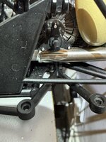
Porsche 917K continuation of build this time adding the torrison bar which had to be threaded through the lower framework to link up with the rear shock absorbers another PIA
Then came the parcel shelves which slot into place at the front of the oil and fuel sub assembly and are then attached to the rear of the subframe with screws from underneath after this you then attach two bracing struts from the base of the parcel shelves to a point on the subframe which in the instructions is wrong again Nigel pointed this out. They had it going to a place that you couldn’t reach where in actual fact there is a different point not shown on the instructions but you can see it on the model as you build it. There’s a small cut out and a hole underneath where you lock the bar in and then attach it to the base of the parcel shelf.
Now the reason they’re called parcel shelves is because according to the rules the cars had to have storage for suitcases so when you look at these parcel shelves which are black and look like mudguards they’ve actually got a piece at the back where a suitcase would fit crazy I know but that was the rules
Also added during this time was the rear lights now following a tip from Nigel I also mounted silver foil into the back of the light before fitting it onto the model. If you look at the photograph you’ll see that the left-hand light is very dull whereas the right hand light is a lot brighter. This is the one got fitted with the foil so afterwards I’ve retrofitted foil into the left one as well Great tip Nige, I will follow that on all my rear lights in future
Anyway with the fitting of these, you are now up-to-date where I am on the Porsche build
 
Thread owner
IMG_4735.jpg Porsche 917K continuing build
This time we’ve added a Bracing Strut over the top of the engine along with the trumpet ends which you can see sticking up just in front of the spare wheel and the spare wheel tie down shackles. These need to dry overnight before I try threading the belt material through them so they don’t pull off with secured them with a sanded down toothpick as in the instructions they were just glued on the top which is no good at all
There is some debate whether these were actually used in real life because some pictures a show like Bungy chords holding the spare wheel in and then others there’s nothing so this could be a bit of artistic license on Pocher is behalf anyway, they were in the instructions so I fitted them
and finally I’ve painted the inside of the body panels as they were the same colour as the outside which is completely wrong following Nigel‘s advice. I painted the back panel black and the rest in a dark grey might be too dark but you’re not gonna see it unless you lift the thing up anyway and it definitely looks better than the blue IMG_4751.jpg they were originally so when the glue is dried, I’ll be strapping in the spare wheel then we come to fit in the body panels after that it’s just the wheels and then it is finished
 
Excellent work. Too bad these models don't come with a recording, as the sounds this mill makes are wild.
 
Thread owner
IMG_4794.jpg IMG_4771.jpg IMG_4772.jpg IMG_4768.png IMG_4769.png IMG_4770.png Assembly in the body panels
so the first thing was to assemble the two doors these are on a sort of angled hinge which then clips into the bodywork and it secured with a bracket across the top which locks both of the hinge points into place
next the front and rear body panels are joined together and again I’ll lock together using bracing bracket after which the rear clear bulkhead which fits into the roof is added this also clips across where the two pieces join and reinforces it
IMG_4785.jpg
 
Thread owner
Click image for larger version  Name:	IMG_4799.jpg Views:	0 Size:	270.2 KB ID:	1265396 Click image for larger version  Name:	IMG_4799.jpg Views:	0 Size:	270.2 KB ID:	1265396 Click image for larger version  Name:	IMG_4799.jpg Views:	0 Size:	270.2 KB ID:	1265396 Click image for larger version  Name:	IMG_4799.jpg Views:	0 Size:	270.2 KB ID:	1265396 
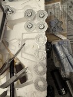
next up assembly in the front lamps these are made of several pieces. or main lamp housing then you have the two lamps followed by the two lenses. All very straightforward until you come fit the large lenses and find out they’re too large to fit around the housing, so you have to sand them down by about a quarter of a millimetre all round to get them to fit
All transparency Work was glued with Contactor Clear which drives clear once it’s set you could also use ordinary contact wood adhesive that tries clear or the one that everybody’s probably familiar with Microscale Crystal Clear my normal go to but I had this Contactor Clear which I’ve never used before so I thought I’d give that a chance to see how it fared up on the results were good so all three of those type of glue will work
once the lights and rear panel were done, there was one last thing to do fit the cockpit glass canopy frame to the inside of the body panels and two rubber hoses that should’ve been fitted in an earlier stage but there was no point because there was nowhere for them to go so they were now fitted at this stage where they’re glued into the front top of the bonnet basically they have outlets at the front of the car which lead into the underneath the dashboard to supply fresh air to the cockpit
And finally joining the subframe to the body panels to say this was painful is an understatement. It wasn’t difficult but it took a lot of fettling to get the panels to lineup sufficiently to enable the screws to be inserted and tightened after about 20 minutes I actually managed to get one screw into place and this pulled the rest of it sufficiently to enable the remaining screws to be added as each screw was added so the panels lined up more and more
Next will be some additional parts added to the under surface I think they’re orange and blue with a black stripe then there’s a large amount of decaling to do as each wheel has five decals on it the wheels will then be assembled and added to the subframe and then you obviously got the numbers to go on the top of the car and the bonnet and the 2 fins on the rear which should complete the model
 
Thread owner
Click image for larger version  Name:	IMG_4807.jpg Views:	0 Size:	323.5 KB ID:	1265514 Porsche 917K continuation first off dry fit the transparency’s to make sure they fit so in the picture above you can see I’ve added the cockpit windscreen the two side windows and on the front the Headlamp covers next we will be adding decals to the wheels
so before the wheels can be fitted onto the car and in the case of the rear wheels before they can be assembled onto the tires, we have to add some decals
I have to say that the decals were superb quality as good as Cartograph’s they went down really smoothly and without a problem mind you they’re only small so you’ve got the big ones to do yet But hopefully they will be the same
After the decals was applied and then coated them with MICROSOL setting solution as you can see from the photograph once this is dried thoroughly I will then assemble the remaining wheels and get them added to the car before we move onto the rest of the decaling
Click image for larger version  Name:	IMG_4807.jpg Views:	0 Size:	323.5 KB ID:	1265514 Click image for larger version  Name:	IMG_4807.jpg Views:	0 Size:	323.5 KB ID:	1265514
 
Back
Top